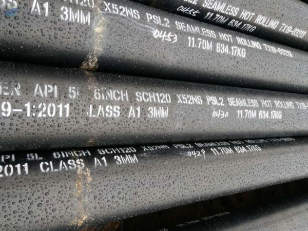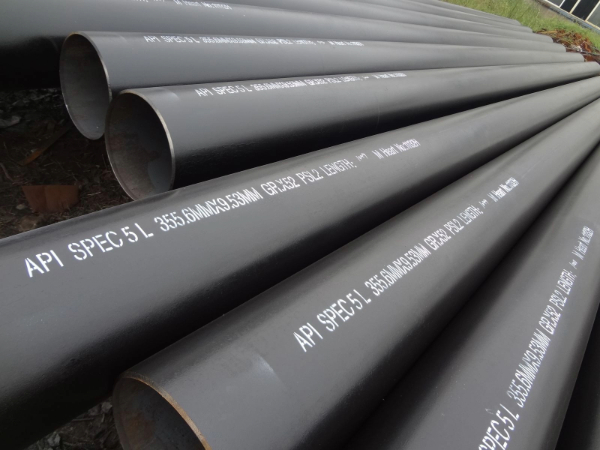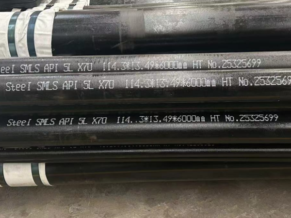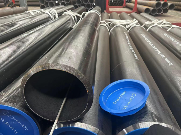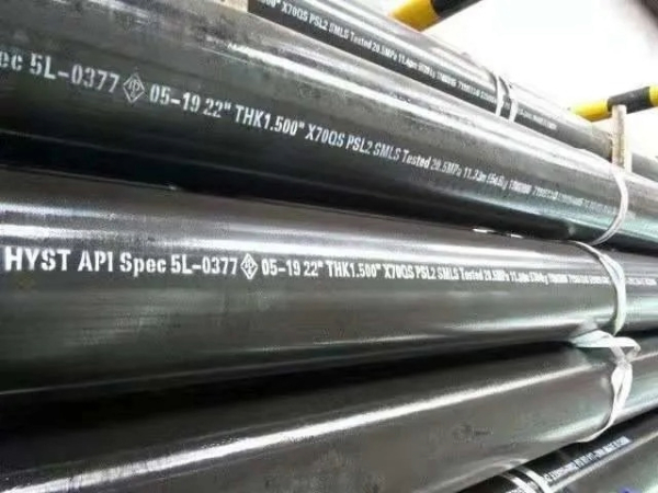
ANSI / API 5L specifies the manufacture of two product levels (PSL1 and PSL2) of seamless and welded steel pipe for the use of a pipeline in the transportation of petroleum and natural gas. For material use in a sour service application, refer to Annex H; for offshore service application, refer to Annex J of API 5L 45th Edition.
In a word, API 5L pipe is the carbon steel pipe applied to the oil and gas transmission system. Meanwhile other fluids like steam, water, slurry also could adopt the API 5L standard for the transmission purposes.
API 5L specification covers the manufacturing types in welded and seamless.
Welded Type: ERW, SAW, DSAW, LSAW, SSAW, HSAW Pipe
For API 5L welded pipe common types as Follows:
ERW: Electric Resistance Welded, for pipe diameter normally under 24 inch.
DSAW/SAW: Double Submerged Arc Welding / Submerged Arc Welding, a substitute welding method than ERW for larger diameter pipes.
LSAW: Longitudinal SAW, for diameter up to 48 inch. Also called JCOE manufacturing process.
SSAW/HSAW: Spiral Subemerged Arc Welded / Helical SAW, pipe diameters up to 100 inch.
Seamless Type: Hot Rolled Seamless and Cold Rolled Seamless Pipe
Seamless manufacturing type usually for the small diameters pipe, normally diameter under 24 inch.
(For the pipe diameter is less than 150 mm or 6 inch, the seamless steel pipe is more applied than steel pipe in welded.)
There are also big diameters seamless pipe. By hot rolled manufacturing process we could get seamless pipe diameters at most 20 inch (508 mm). But if you need the seamless pipe more than 20", we can get it through hot expanding processes, maximum diameters to 40 inch 1016 mm.
| PSL | Delivery Condition | Pipe grade |
| PSL1 | As-rolled, normalized, normalizing formed | A |
| As-rolled, normalizing rolled, thermomechanical rolled, thermo-mechanical formed, normalizing formed, normalized, normalized and tempered or if agreed Q&T SMLS only | B | |
| As-rolled, normalizing rolled, thermomechanical rolled, thermo-mechanical formed, normalizing formed, normalized, normalized and tempered | X42, X46, X52, X56, X60, X65, X70 | |
| PSL2 | As-rolled | BR, X42R |
| Normalizing rolled, normalizing formed, normalized or normalized and tempered | BN, X42N, X46N, X52N, X56N, X60N | |
| Quenched and tempered | BQ, X42Q, X46Q, X56Q, X60Q, X65Q, X70Q, X80Q, X90Q, X100Q | |
| Thermomechanical rolled or thermomechanical formed | BM, X42M, X46M, X56M, X60M, X65M, X70M, X80M | |
| Thermomechanical rolled | X90M, X100M, X120M | |
| The suffice (R, N, Q or M) for PSL2 grades, belongs to the steel grade |
| Steel Grade | Mass fraction, % based on heat and product analyses a,g | ||||||
| C | Mn | P | S | V | Nb | Ti | |
| max b | max b | max | max | max | max | max | |
| Seamless Pipe | |||||||
| A | 0.22 | 0.9 | 0.3 | 0.3 | – | – | – |
| B | 0.28 | 1.2 | 0.3 | 0.3 | c,d | c,d | d |
| X42 | 0.28 | 1.3 | 0.3 | 0.3 | d | d | d |
| X46 | 0.28 | 1.4 | 0.3 | 0.3 | d | d | d |
| X52 | 0.28 | 1.4 | 0.3 | 0.3 | d | d | d |
| X56 | 0.28 | 1.4 | 0.3 | 0.3 | d | d | d |
| X60 | 0.28 e | 1.40 e | 0.3 | 0.3 | f | f | f |
| X65 | 0.28 e | 1.40 e | 0.3 | 0.3 | f | f | f |
| X70 | 0.28 e | 1.40 e | 0.3 | 0.3 | f | f | f |
| Welded Pipe | |||||||
| A | 0.22 | 0.9 | 0.3 | 0.3 | – | – | – |
| B | 0.26 | 1.2 | 0.3 | 0.3 | c,d | c,d | d |
| X42 | 0.26 | 1.3 | 0.3 | 0.3 | d | d | d |
| X46 | 0.26 | 1.4 | 0.3 | 0.3 | d | d | d |
| X52 | 0.26 | 1.4 | 0.3 | 0.3 | d | d | d |
| X56 | 0.26 | 1.4 | 0.3 | 0.3 | d | d | d |
| X60 | 0.26 e | 1.40 e | 0.3 | 0.3 | f | f | f |
| X65 | 0.26 e | 1.45 e | 0.3 | 0.3 | f | f | f |
| X70 | 0.26e | 1.65 e | 0.3 | 0.3 | f | f | f |
|
a. Cu ≤ 0.50%; Ni ≤ 0.50%; Cr ≤ 0.50%; and Mo ≤ 0.15% b. For each reduction of 0.01% below the specified maximum concentration for carbon, an increase of 0.05% above the specified maximum concentration for Mn is permissible, up to a maximum of 1.65% for grades ≥ L245 or B, but ≤ L360 or X52; up to a maximum of 1.75% for grades > L360 or X52, but < L485 or X70; and up to a maximum of 2.00% for grade L485 or X70. c. Unless otherwise agreed NB + V ≤ 0.06% d. Nb + V + Ti ≤ 0.15% e. Unless otherwise agreed f. Unless otherwise agreed, Nb + V + Ti ≤ 0.15% g. No deliberate addition of B is permitted and the residual B ≤ 0.001% |
|||||||
| Steel Grade | Mass fraction, % based on heat and product analyses | Carbon Equiv a | ||||||||||||||||||
| C | Si | Mn | P | S | V | Nb | Ti | Other | CE IIW | CE Pcm | ||||||||||
| max b | max | max b | max | max | max | max | max | max | max | |||||||||||
| Seamless and Welded Pipe | ||||||||||||||||||||
| BR | 0.24 | 0.4 | 1.2 | 0.025 | 0.015 | c | c | 0.04 | e,l | 0.43 | 0.25 | |||||||||
| X42R | 0.24 | 0.4 | 1.2 | 0.025 | 0.015 | 0.06 | 0.05 | 0.04 | e,l | 0.43 | 0.25 | |||||||||
| BN | 0.24 | 0.4 | 1.2 | 0.025 | 0.015 | c | c | 0.04 | e,l | 0.43 | 0.25 | |||||||||
| X42N | 0.24 | 0.4 | 1.2 | 0.025 | 0.015 | 0.06 | 0.05 | 0.04 | e,l | 0.43 | 0.25 | |||||||||
| X46N | 0.24 | 0.4 | 1.4 | 0.025 | 0.015 | 0.07 | 0.05 | 0.04 | d,e,l | 0.43 | 0.25 | |||||||||
| X52N | 0.24 | 0.45 | 1.4 | 0.025 | 0.015 | 0.1 | 0.05 | 0.04 | d,e,l | 0.43 | 0.25 | |||||||||
| X56N | 0.24 | 0.45 | 1.4 | 0.025 | 0.015 | 0.10f | 0.05 | 0.04 | d,e,l | 0.43 | 0.25 | |||||||||
| X60N | 0.24f | 0.45f | 1.40f | 0.025 | 0.015 | 0.10f | 0.05f | 0.04f | g,h,l | As agreed | ||||||||||
| BQ | 0.18 | 0.45 | 1.4 | 0.025 | 0.015 | 0.05 | 0.05 | 0.04 | e,l | 0.43 | 0.25 | |||||||||
| X42Q | 0.18 | 0.45 | 1.4 | 0.025 | 0.015 | 0.05 | 0.05 | 0.04 | e,l | 0.43 | 0.25 | |||||||||
| X46Q | 0.18 | 0.45 | 1.4 | 0.025 | 0.015 | 0.05 | 0.05 | 0.04 | e,l | 0.43 | 0.25 | |||||||||
| X52Q | 0.18 | 0.45 | 1.5 | 0.025 | 0.015 | 0.05 | 0.05 | 0.04 | e,l | 0.43 | 0.25 | |||||||||
| X56Q | 0.18 | 0.45f | 1.5 | 0.025 | 0.015 | 0.07 | 0.05 | 0.04 | e,l | 0.43 | 0.25 | |||||||||
| X60Q | 0.18f | 0.45f | 1.70f | 0.025 | 0.015 | g | g | g | h,l | 0.43 | 0.25 | |||||||||
| X65Q | 0.18f | 0.45f | 1.70f | 0.025 | 0.015 | g | g | g | h,l | 0.43 | 0.25 | |||||||||
| X70Q | 0.18f | 0.45f | 1.80f | 0.025 | 0.015 | g | g | g | h,l | 0.43 | 0.25 | |||||||||
| X80Q | 0.18f | 0.45f | 1.90f | 0.025 | 0.015 | g | g | g | i,j | As agreed | ||||||||||
| Welded Pipe | ||||||||||||||||||||
| BM | 0.22 | 0.45 | 1.2 | 0.025 | 0.015 | 0.05 | 0.05 | 0.04 | e,l | 0.43 | 0.25 | |||||||||
| X42M | 0.22 | 0.45 | 1.3 | 0.025 | 0.015 | 0.05 | 0.05 | 0.04 | e,l | 0.43 | 0.25 | |||||||||
| X46M | 0.22 | 0.45 | 1.3 | 0.025 | 0.015 | 0.05 | 0.05 | 0.04 | e,l | 0.43 | 0.25 | |||||||||
| X52M | 0.22 | 0.45 | 1.4 | 0.025 | 0.015 | d | d | d | e,l | 0.43 | 0.25 | |||||||||
| X56M | 0.22 | 0.45f | 1.4 | 0.025 | 0.015 | d | d | d | e,l | 0.43 | 0.25 | |||||||||
| X60M | 0.12f | 0.45f | 1.60f | 0.025 | 0.015 | g | g | g | h,l | 0.43 | 0.25 | |||||||||
| X65M | 0.12f | 0.45f | 1.60f | 0.025 | 0.015 | g | g | g | h,l | 0.43 | 0.25 | |||||||||
| X70M | 0.12f | 0.45f | 1.70f | 0.025 | 0.015 | g | g | g | h,l | 0.43 | 0.25 | |||||||||
| X80M | 0.12f | 0.45f | 1.85f | 0.025 | 0.015 | g | g | g | i,j | 0.43f | 0.25 | |||||||||
| Pipe Grade | Tensile Properties – Pipe Body of SMLS and Welded Pipes PSL 1 | Seam of Welded Pipe | ||
| Yield Strength a | Tensile Strength a | Elongation | Tensile Strength b | |
| Rt0,5 PSI Min | Rm PSI Min | (in 2in Af % min) | Rm PSI Min | |
| A | 30,500 | 48,600 | c | 48,600 |
| B | 35,500 | 60,200 | c | 60,200 |
| X42 | 42,100 | 60,200 | c | 60,200 |
| X46 | 46,400 | 63,100 | c | 63,100 |
| X52 | 52,200 | 66,700 | c | 66,700 |
| X56 | 56,600 | 71,100 | c | 71,100 |
| X60 | 60,200 | 75,400 | c | 75,400 |
| X65 | 65,300 | 77,500 | c | 77,500 |
| X70 | 70,300 | 82,700 | c | 82,700 |
| a. For intermediate grade, the difference between the specified minimum tensile strength and the specified minimum yield for the pipe body shall be as given for the next higher grade. | ||||
| b. For the intermediate grades, the specified minimum tensile strength for the weld seam shall be the same as determined for the body using foot note a. | ||||
| c. The specified minimum elongation, Af, expressed in percent and rounded to the nearest percent, shall be determined using the following equation. | ||||
| Specified Outside Diameter D (in) | Diameter Tolerance, inches d | Out-of-Roundness Tolerance in | ||||
| Pipe except the end a | Pipe end a,b,c | Pipe except the End a | Pipe End a,b,c | |||
| SMLS Pipe | Welded Pipe | SMLS Pipe | Welded Pipe | |||
| < 2.375 | -0.031 to + 0.016 | -0.031 to + 0.016 | 0.048 | 0.036 | ||
| ≥2.375 to 6.625 | +/- 0.0075D | -0.016 to + 0.063 | 0.020D | 0.015D | ||
| >6.625 to 24.000 | +/- 0.0075D | +/- 0.0075D, but max of 0.125 | +/- 0.005D, but max of 0.063 | 0.020D | 0.015D | |
| >24 to 56 | +/- 0.01D | +/- 0.005D but max of 0.160 | +/- 0.079 | +/- 0.063 | 0.015D but max of 0.060 | 0.01D but max of 0.500 |
| >56 | As agreed | |||||
| a. The pipe end includes a length of 4 in at each of the pipe extremities | ||||||
| b. For SMLS pipe the tolerance apply for t≤0.984in and the tolerances for the thicker pipe shall be as agreed | ||||||
| c. For expanded pipe with D≥8.625in and for non-expanded pipe, the diameter tolerance and the out-of-roundness tolerance may be determined using the calculated inside diameter or measured inside diameter rather than the specified OD. | ||||||
| d. For determining compliance to diameter tolerance, the pipe diameter is defined as the circumference of the pipe in any circumferential plane divide by Pi. | ||||||
| Wall thickness | Tolerances a |
| t inches | inches |
| SMLS pipe b | |
| ≤ 0.157 | -1.2 |
| > 0.157 to < 0.948 | + 0.150t / – 0.125t |
| ≥ 0.984 | + 0.146 or + 0.1t, whichever is the greater |
| – 0.120 or – 0.1t, whichever is the greater | |
| Welded pipe c,d | |
| ≤ 0.197 | +/- 0.020 |
| > 0.197 to < 0.591 | +/- 0.1t |
| ≥ 0.591 | +/- 0.060 |
| a. If the purchase order specifies a minus tolerance for wall thickness smaller than the applicable value given in this table, the plus tolerance for wall thickness shall be increased by an amount sufficient to maintain the applicable tolerance range. | |
| b. For pipe with D≥ 14.000 in and t≥0.984in, the wall thickness tolerance locally may exceed the plus tolerance for wall thickness by an additional 0.05t provided that the plus tolerance for mass is not exceeded. | |
| c. The plus tolerance for wall thickens does not apply to the weld area | |
| d. See the full API5L spec for full details | |
API 5L Steel Pipe Tolerance on Dimensions
|
Standard |
Out Diameter |
Wall Thickness |
|
|
API 5L |
Tolerance |
Tolerance |
|
|
D<60.3 |
+0.41mm, -0.80mm |
+15.0%, -12.5% |
|
|
D≥60.3 |
+0.75%D, -0.75%D |
+15.0%, -12.5% | |
Chemical Analysis (%) of API 5L Line Pipe
|
Standard |
Class |
Grade |
|
Yield strength not less than (MPa) |
Tensile strength (MPa) |
Elongation(%) |
Y.S/T.S |
|
API SPEC 5L ISO 3183 |
PLS1 |
L245B |
min |
245 |
415 |
b |
- |
|
L290X42 |
min |
290 |
415 |
b |
- |
||
|
L320X46 |
min |
320 |
435 |
b |
- |
||
|
L360X52 |
min |
360 |
460 |
b |
- |
||
|
L390X56 |
min |
390 |
490 |
b |
- |
||
|
L415X60 |
min |
415 |
520 |
b |
- |
||
|
L450X60 |
min |
450 |
535 |
b |
- |
||
|
L485X70 |
min |
485 |
570 |
b |
- |
||
|
PLS2 |
L245N BN |
min |
245 |
415 |
b |
- |
|
|
L245M BM |
max |
450 |
760 |
b |
0.93 |
||
|
L290NX42N |
min |
290 |
415 |
b |
- |
||
|
L290MX42M |
max |
495 |
760 |
b |
0.93 |
||
|
L320NX46N |
min |
320 |
435 |
b |
- |
||
|
L320MX46M |
max |
525 |
760 |
b |
0.93 |
||
|
L360NX52N |
min |
360 |
460 |
b |
- |
||
|
L360MX52M |
max |
530 |
760 |
b |
0.93 |
||
|
L390NX56N |
min |
390 |
490 |
b |
- |
||
|
L390MX56M |
max |
545 |
760 |
b |
0.93 |
||
|
L415NX60N |
min |
415 |
520 |
b |
- |
||
|
L415MX60M |
max |
565 |
760 |
b |
0.93 |
||
|
L450MX65M |
min |
450 |
535 |
b |
- |
||
|
max |
600 |
760 |
b |
0.93 |
|||
|
L485MX70M |
min |
485 |
570 |
b |
- |
||
|
max |
635 |
760 |
b |
0.93 |
|||
|
L555MX80M |
min |
555 |
625 |
b |
- |
||
|
max |
705 |
825 |
b |
0.93 |
|
Standard |
Type of pipe |
Class |
Grade |
C |
Si |
Mn |
P |
S |
V |
Nb |
Ti |
|
max |
max |
max |
max |
max |
max |
max |
max |
||||
|
API SPEC 5L |
SMLS |
PLS1 |
L245 B L290 X42 L320 X46 L360 X52 L390 X56 L415 X60 L450 X65 L485 X70 L245N BN |
0.28 0.28 0.28 0.28 0.28 0.28 0.28 0.28 0.24 |
0.4 |
1.20 1.30 1.40 1.40 1.40 1.40 1.40 1.40 1.20 |
0.030 0.030 0.030 0.030 0.030 0.030 0.030 0.030 0.025 |
0.030 0.030 0.030 0.030 0.030 0.030 0.030 0.030 0.015 |
——— |
——— |
0.04 |
|
PLS2 |
L290N X42N |
0.24 |
0.4 |
1.2 |
0.025 |
0.015 |
0.06 |
0.05 |
0.04 |
||
|
L320N X46N |
0.24 |
0.4 |
1.4 |
0.025 |
0.015 |
0.07 |
0.05 |
0.04 |
|||
|
L360N X52N |
0.24 |
0.45 |
1.4 |
0.025 |
0.015 |
0.1 |
0.05 |
0.04 |
|||
|
L390N X56N |
0.24 |
0.45 |
1.4 |
0.025 |
0.015 |
0.1 |
0.05 |
0.04 |
|||
|
L415N X60N |
0.24 |
0.45 |
1.4 |
0.025 |
0.015 |
0.1 |
0.05 |
0.04 |
|||
|
WELD |
PLS1 |
L245 B |
0.26 |
- |
1.2 |
- |
0.03 |
0.03 |
- |
- |
|
|
L290 X42 |
0.26 |
- |
1.3 |
- |
0.03 |
0.03 |
- |
- |
|||
|
L320 X46 |
0.26 |
- |
1.4 |
- |
0.03 |
0.03 |
- |
- |
|||
|
L360 X52 |
0.26 |
- |
1.4 |
- |
0.03 |
0.03 |
- |
- |
|||
|
L390 X56 |
0.26 |
- |
1.4 |
- |
0.03 |
0.03 |
- |
- |
|||
|
L415 X60 |
0.26 |
- |
1.4 |
- |
0.03 |
0.03 |
- |
- |
|||
|
L450 X65 |
0.26 |
- |
1.45 |
- |
0.03 |
0.03 |
- |
- |
|||
|
L485 X70 |
0.26 |
- |
1.65 |
- |
0.03 |
0.03 |
- |
- |
|||
|
PLS2 |
L245M BM |
0.22 |
0.45 |
1.2 |
0.025 |
0.015 |
0.05 |
0.05 |
0.04 |
||
|
L290M X42M |
0.22 |
0.45 |
1.3 |
0.025 |
0.015 |
0.05 |
0.05 |
0.04 |
|||
|
L320M X46M |
0.22 |
0.45 |
1.3 |
0.025 |
0.015 |
0.05 |
0.05 |
0.04 |
|||
|
L360M X52M |
0.22 |
0.45 |
1.4 |
0.025 |
0.015 |
- |
- |
- |
|||
|
L390M X56M |
0.22 |
0.45 |
1.4 |
0.025 |
0.015 |
- |
- |
- |
|||
|
L415M X60M |
0.12 |
0.45 |
1.6 |
0.025 |
0.015 |
- |
- |
- |
|||
|
L450M X65M |
0.12 |
0.45 |
1.6 |
0.025 |
0.015 |
- |
- |
- |
|||
|
L485M X70M |
0.12 |
0.45 |
1.7 |
0.025 |
0.015 |
- |
- |
- |
|||
|
L555M X80M |
0.12 |
0.45 |
1.85 |
0.025 |
0.015 |
- |
- |
- |
PSL2 is PSL1 + stricter requirements:
Chemical:
(1) Carbon equivalent CE(IIW) ≤ 0.43% — PSL1 allows up to 0.50%
(2) Carbon ≤ 0.24% — restricts weld cracks
Mechanical:
(3) Yield strength upper limit — prevents over-strength issues
(4) CVN impact mandatory at all thicknesses — PSL1 optional > 10mm
(5) DWTT (Drop Weight Tear Test) for PSL2 — critical for brittle fracture
Testing:
(6) 100% UT of weld seam — PSL1 allows spot testing
(7) Dimensional tolerances tighter
PSL2 required for: gas transmission, offshore, sour service, cold climate.
The 22 HRC rule per NACE MR0175/ISO 15156:
Why hardness?
H₂S dissociates at the steel surface → H atoms diffuse in →
High hardness = high strength = high stress = cracking
The limit:
22 HRC (or 250 HV10) = ~280 MPa yield strength
How to achieve:
(1) Normalize — reduces hardness to ~180 HB
(2) Quench + Temper — control hardness distribution
(3) TMCP — thermo-mechanical controlled processing
Check: through-thickness hardness survey required.
Seamless preferred when:
(1) OD ≤ 20" (500mm) — above this, welded more economical
(2) Weld factor E = 1.0 (no discount vs seamless)
(3) Threaded ends required — welded threads can crack
(4) Low-temperature service — no weld = no stress riser
(5) Sour service — weld HAZ cracks in sour service
Welded is OK when:
Gas pipeline with 100% UT and proper weld factor (E=0.95 or 1.0)
Cost comparison: Seamless ~15-20% premium over LSAW
The CVN test for brittle fracture prevention:
API 5L requirement:
PSL2: min 20J avg at 0°C for sour service
For cold climates, additional requirements:
Grade B at -20°C: min 20J (single test >= 15J)
X52+ at -30°C: per project specification
Why CVN matters:
Brittle fracture propagates at near-sonic velocity.
Fracture-arrest design uses CVN data.
Temperature adjustment:
+/-5°C per 2J (for samples less than full thickness).
Pipeline Internal Gas Compressor (Pig) clearance design:
Rule of thumb: ID clearance = 2.5% to 5% of pipe ID
Example: 20" (508mm) → 12.7-25.4mm clearance
Why clearance:
(1) Wax and paraffin buildup
(2) Mechanical damage tolerance
(3) Thermal expansion margin
Calculation: ID = OD - 2 × WT
ID must be: pig OD / 0.95 minimum
For batch transportation, tighter clearances possible.
Field welding high-strength line pipe requires:
Weld metal matching:
(1) Match or slightly overmatch base metal yield
(2) Weld wire must be ≥ X70 strength
Pre-heat requirements:
(3) X70+ requires 100-150°C preheat for HAZ cracking
Post-weld treatment:
(4) May require stress relief for sour service
Common issues:
(5) Lack of fusion at root — inspection critical
(6) Hydrogen cracking — keep electrodes dry
Procedure: AWS D1.1 + API 1104 required for qualification.