
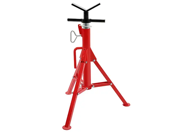
Pipe Stands Types:
Pipe Roller Stands
These are also referred to as a V Head pipe stand and they allow the user to maneuver or turn very heavy and tall pipes during fabrication or welding steel. Many fabricators prefer these because of the ability to move heavy pipes relatively easily.
Screw Jack Stands
These pipe jack stands allow the user to adjust the height, giving more flexibility on the job by allowing them to make large or small adjustments during the fabrication process.
Adjustable Pipe Stands
These are like screw jack stands as they are adjustable as well but come in different styles by different brands like the Sumner Max Jax, Mathey Dearman, Rigid, Wheeler Rex, and Reed Mfg.
Welding Stands
Welding stands are specifically made for harsh welding environments and handle black and stainless steel pipe in fabrication processes such as ship building and oil pipelines.
V Head Pipe Stand
A V stand is in the shape of a V to hold pipe in place. These come with different options that can be added on, options include a v head ball transfers that have a large metal ball on it that can be added for moving pipe during fabrication.
Sumner Pipe Stands
Sumner pipe stands are known in the industry for their Sumner max jax/jack, these are super heavy-duty pipe stands for welding and have 2500 pound capacity, many fabricators use multiple Sumner max jacks in their shop for big jobs in the oilfield.
Pipe Stands Specification:
V Head Pipe Stand
|
Description |
Height Adjustment Low-High |
Max. Pipe Capacity |
Max. Weight Capacity |
Weight |
||||
|
in. |
cm |
in. |
mm |
lb. |
kg |
lb. |
kg |
|
|
V Head Low Pipe Stand |
20 - 38 |
51 - 96 |
12 |
300 |
2500 |
1134 |
21 |
9.5 |
|
V Head High Pipe Stand |
28 - 53 |
71 - 135 |
23 |
10.4 10.9 |
||||
|
V Head High Folding Pipe Stand |
28 - 51 |
71 - 131 |
24 |
|||||
Pipe Roller Stands
|
Description |
Height Adjustment Low-High |
Max. Pipe Capacity |
Max. Weight Capacity |
Weight |
||||
|
in. |
cm |
in. |
mm |
lb. |
kg |
lb. |
kg |
|
|
Roller Head Low Pipe Stand |
24 - 42 |
61 - 107 |
12 |
300 |
1000 |
454 |
24 |
10.9 |
|
Roller Head High Pipe Stand |
32 - 55 |
81 - 142 |
27 |
12.3 |
||||
Adjustable Pipe Stands
|
Model No. |
Description |
Height Adjustment Low-High |
Max. Pipe Capacity |
Max. Weight Capacity |
Weight |
||||
|
in. |
cm |
in. |
mm |
lb. |
kg |
lb. |
kg |
||
|
46 |
Adjustable Pipe Support |
23 - 33 |
58- 84 |
6 |
150 |
2500 |
1134 |
23 |
10.4 |
|
92 |
32 - 41 |
81 - 104 |
28 |
12.7 |
|||||
|
965 |
Support Stand for Groovers |
26 - 42 |
66 - 107 |
12 |
300 |
2500 |
1134 |
29 |
13.2 |
Roller stands (single-axis rotation) feature steel tube or cylindrical rollers with sealed ball bearings (ABEC-5 or ABEC-7 precision). Roller rotation eliminates circumferential welding seams that create incomplete fusion at start/stop positions during orbital GTAW or SAW processes. Typical orbital weld requirements: radial runout below 0.25mm, surface speed 100-300mm/min for consistent heat input.
V-head stands provide static pipe support with 90° included angle V-cradle (standard) or 120° for larger diameters. V-profile centers pipe weight on stand frame, eliminating lateral rolling tendency during cutting, fitting, or tack welding operations. Removable V-inserts permit quick changeover between pipe sizes without stand replacement.
Hybrid configuration for pipeline fabrication: Lead V-stand positions pipe at weld station; 2-3 trailing roller stands maintain consistent elevation and permit axial pipe advance as welding progresses. Spacing calculated to limit pipe deflection below L/500 between supports where L = span length in mm. Maximum sag at span center = L²/(800×R) where R = pipe radius in mm.
Capacity determination follows cantilever beam analysis for single-point load (pipe weight at stand center). Maximum bending moment M = W×L/4 where W = total load (pipe + water + insulation), L = effective span. Combined stress σ = M×c/I + V×A ensuring σ < 0.6×Fy (yield) with 1.5 factor of safety.
Roller bearing load rating: Dynamic load rating (C) per ISO 281: C = 0.05 × bearing pitch diameter × number of rollers × roller length × contact angle factor. Sealed precision bearings rated 2,000-50,000 lbs dynamic capacity depending on bore size. Replace bearings when radial play exceeds 0.05mm or running torque increases 200% from baseline.
Height-to-capacity relationship: Screw jack stands lose effective capacity as extension increases. At full extension (1.5× collapsed height), capacity reduces to 60% of rated value due to column buckling. Intermediate height positions provide optimal capacity-to-stability balance.
Screw adjustment (acme thread, 6-10 TPI): Manual cranking provides infinite height adjustment within range. Thread pitch determines adjustment speed: coarse thread (6 TPI) faster but less precise. Typical screw jack stands: 450-750mm collapsed, 750-1200mm extended. Capacity loss at full extension 40-50% due to column instability.
Hydraulic gas spring: Single-lever pneumatic assist permits 5-15 second adjustment cycle versus 30-60 seconds for screw type. Gas strut pressure-tuned to support specific load range—oversized struts cause violent extension, undersized prevent height maintenance. Service temperature range -20°C to +60°C; performance degradation above 40°C requires nitrogen recharge.
Pin-and-hole detent: Fixed height positions (typically 150mm increments) via quick-release pin. Maximum stability at each detent position—suitable for production welding with consistent pipe diameter. Not recommended for mixed-diameter fabrication requiring continuous height adjustment.
Powder coating (60-80μm DFT, thermoset polyester): Standard industrial finish providing 500+ hour salt spray resistance per ASTM B117. Color coding per ANSI/HI 9.6.2 (pump suction = yellow, discharge = green, drain = gray) aids identification during maintenance. Impact resistance 1.5N·m without chipping; touch-up with matching liquid coating for damaged areas.
Hot-dip galvanizing (ASTM A123, 45-85μm DFT): Zinc-iron alloy layers provide 20-30 year service life in outdoor storage yards and marine fabrication facilities. Bolted assembly preferred over welded—galvanized components cannot be reworked after fabrication without removing original coating. Specify HDG after fabrication for maximum protection.
Roller surface treatment: Induction-hardened roller surfaces (HRC 55-60) resist abrasive wear from pipe scale and weld spatter. Chrome plating (25-50μm) provides additional surface hardness and corrosion resistance for high-cycle applications. Replace rollers when diameter wear exceeds 5% of original diameter or radial runout exceeds 0.5mm.
Heavy wall pipe stands (10-50 ton capacity): Required for offshore pipe-in-pipe fabrication, subsea flowline manufacturing, and nuclear power piping systems. Features twin V-cradles or dual roller sets to distribute concentrated loads. Extended base plates (minimum 600×600mm) with anchor bolt provisions for seismic Zone 4 applications.
Adjustable track systems: Roller conveyor integrated into fabrication jig permitting continuous pipe advancement without lifting. Modular sections (1m, 2m, 3m lengths) configure to shop floor layout. Drive motor option (0.25-0.75kW variable frequency) for automated pipe feeding during automated welding operations.
Stainless steel construction (304L/316L): Mandatory for pharmaceutical, food-processing, and ultra-pure water piping systems. Electropolished finish (Ra < 0.8μm) prevents contamination and facilitates cleanroom sterility. Non-marking polymer rollers or UHMWPE inserts prevent stainless pipe OD scratching.
ASME B31.3 Process Piping: Pipe supports must accommodate thermal expansion displacements calculated per Appendix V. Stands positioned at calculated guides and anchors to prevent sustained pipe stress exceeding 0.75×Sm ( allowable stress range) at operating temperature.
ASME Section I Power Piping: Supports forBoiler external piping require calculations per PG-58.3. Design loads include pipe weight, insulation, water, steam, and dynamic loads from startup/shutdown transients. Weld attachment to pressure-containing components requires PWHT if base metal exceeds 19mm thickness.
API 1104 Pipeline Welding: Stands must maintain pipe alignment within 1.5mm root face mismatch tolerance throughout circumferential weld sequence. Stands with locking casters (4× braking wheels minimum for pipe <12" OD; 6+ wheels for larger) maintain position during internal alignment equipment deployment.