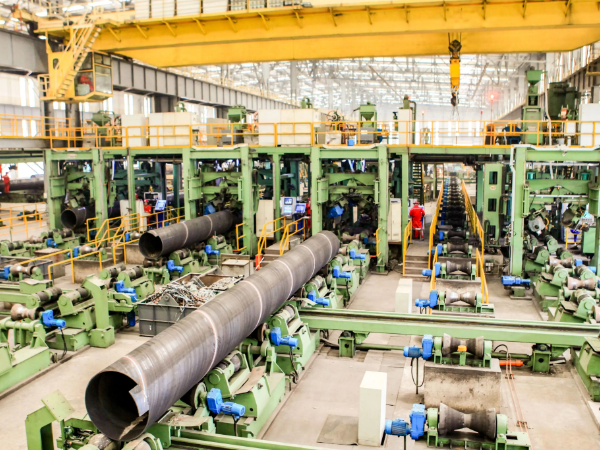
SSAW Steel Pipe Introduction
|
Product:
|
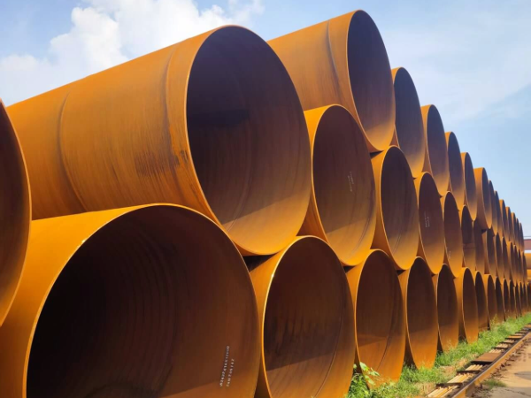
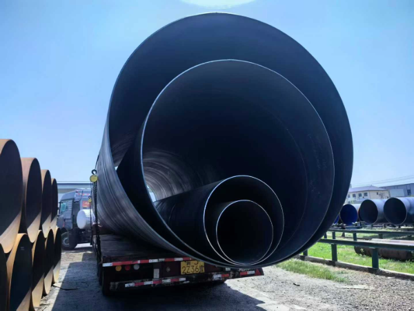
SSAW Pipe,Spirally Submerged Arc Welding Pipe, Sprial Steel Pipe
|
|
Application:
|
Used for Oil/Gas/Water transmission,Construction & Structure Parts
|
|
Size:
|
OD: 219mm-4064mm
|
|
WT: 3.2-40mm
|
|
LENGTH: 5.8/6/11.8/12m
|
|
Pipe Standard:
|
API 5L PSL1/PSL2 Gr.A,Gr.B,X42,X46,X52,X56,X60,X65,X70
|
|
ASTM A53 ASTM 139
|
|
ASTM A252 Grade 1/2/3
|
|
AN/NZS 1163
|
|
EN10219-1 EN10217-1 EN10208
|
Specification of SSAW Pipe
|
OUT DIAMETER
|
WALL THICKNESS (MM)
|
|
mm
|
6
|
7
|
8
|
9
|
10
|
11
|
12
|
13
|
14
|
15
|
16
|
17
|
18
|
19
|
20
|
21
|
22
|
23
|
24
|
25
|
|
219.1
|
.
|
.
|
.
|
.
|
|
|
|
|
|
|
|
|
|
|
|
|
|
|
|
|
|
273
|
.
|
.
|
.
|
.
|
.
|
|
|
|
|
|
|
|
|
|
|
|
|
|
|
|
|
323.9
|
.
|
.
|
.
|
.
|
.
|
.
|
.
|
|
|
|
|
|
|
|
|
|
|
|
|
|
|
325
|
.
|
.
|
.
|
.
|
.
|
.
|
.
|
|
|
|
|
|
|
|
|
|
|
|
|
|
|
355.6
|
.
|
.
|
.
|
.
|
.
|
.
|
.
|
|
|
|
|
|
|
|
|
|
|
|
|
|
|
377
|
.
|
.
|
.
|
.
|
.
|
.
|
.
|
.
|
|
|
|
|
|
|
|
|
|
|
|
|
|
406.4
|
.
|
.
|
.
|
.
|
.
|
.
|
.
|
|
|
|
|
|
|
|
|
|
|
|
|
|
|
426
|
.
|
.
|
.
|
.
|
.
|
.
|
.
|
|
|
|
|
|
|
|
|
|
|
|
|
|
|
457
|
.
|
.
|
.
|
.
|
.
|
.
|
.
|
|
|
|
|
|
|
|
|
|
|
|
|
|
|
478
|
.
|
.
|
.
|
.
|
.
|
.
|
.
|
|
|
|
|
|
|
|
|
|
|
|
|
|
|
508
|
.
|
.
|
.
|
.
|
.
|
.
|
.
|
|
.
|
|
|
|
|
|
|
|
|
|
|
|
|
529
|
.
|
.
|
.
|
.
|
.
|
.
|
.
|
|
.
|
|
|
|
|
|
|
|
|
|
|
|
|
630
|
.
|
.
|
.
|
.
|
.
|
.
|
.
|
|
.
|
.
|
|
|
|
|
|
|
|
|
|
|
|
711
|
.
|
.
|
.
|
.
|
.
|
.
|
.
|
.
|
.
|
.
|
.
|
|
|
|
|
|
|
|
|
|
|
720
|
.
|
.
|
.
|
.
|
.
|
.
|
.
|
.
|
.
|
.
|
.
|
|
|
|
|
|
|
|
|
|
|
813
|
|
.
|
.
|
.
|
.
|
.
|
.
|
.
|
.
|
.
|
.
|
.
|
.
|
|
|
|
|
|
|
|
|
820
|
|
.
|
.
|
.
|
|
.
|
.
|
.
|
.
|
.
|
.
|
.
|
.
|
|
|
|
|
|
|
|
|
920
|
|
|
.
|
.
|
|
.
|
.
|
.
|
.
|
.
|
.
|
.
|
.
|
|
|
|
|
|
|
|
|
1020
|
|
|
.
|
.
|
.
|
.
|
.
|
.
|
.
|
.
|
.
|
.
|
.
|
.
|
.
|
|
|
|
|
|
|
1220
|
|
|
.
|
.
|
.
|
.
|
.
|
.
|
.
|
.
|
.
|
.
|
.
|
.
|
.
|
|
|
|
|
|
|
1420
|
|
|
|
.
|
.
|
.
|
.
|
.
|
.
|
.
|
|
.
|
.
|
.
|
.
|
|
|
|
|
|
|
1620
|
|
|
|
|
.
|
.
|
.
|
.
|
.
|
.
|
.
|
.
|
.
|
.
|
.
|
|
|
|
|
|
|
1820
|
|
|
|
|
|
.
|
.
|
.
|
.
|
.
|
.
|
.
|
.
|
.
|
.
|
|
|
|
|
|
|
2020
|
|
|
|
|
|
|
.
|
.
|
.
|
.
|
.
|
.
|
.
|
.
|
.
|
|
|
|
|
|
|
2220
|
|
|
|
|
|
|
|
.
|
.
|
.
|
.
|
.
|
.
|
.
|
.
|
|
|
|
|
|
|
2500
|
|
|
|
|
|
|
|
.
|
.
|
.
|
.
|
.
|
.
|
.
|
.
|
.
|
.
|
.
|
.
|
.
|
|
2540
|
|
|
|
|
|
|
|
|
.
|
.
|
.
|
.
|
.
|
.
|
.
|
.
|
.
|
.
|
.
|
.
|
|
3500
|
|
|
|
|
|
|
|
|
|
.
|
.
|
.
|
.
|
.
|
.
|
.
|
.
|
.
|
.
|
.
|
Standard and Classification of SSAW Steel Pipe
|
CLASSFICATION
|
STANDARD
|
MAIN PRODUCTS
|
|
Steel Pipe for Fluid Service
|
GB/T 14291
|
Welded pipe for mine fluid sevice
|
|
GB/T 3091
|
Welded pipe for low pressure fluid service
|
|
SY/T 5037
|
Spirally submerged arc welded steel pipe for pipelines for low pressure fluid service
|
|
ASTM A53
|
Black and hot-hipped galvanized welded and seamless steel pipe
|
|
BS EN10217-2
|
Welded steel tybes for pressure purposes - delivery technical conditions - part2: Electric welded non- alloy and alloy steel tubes with specified elevated temperature properties
|
|
BS EN10217-5
|
Welded steel tybes for pressure purposes - delivery technical conditions - part5: submerged arc welded non-alloy and alloy steel tubes with specified elevated temperature properties
|
|
Steel Pipe for Ordinary Structure
|
GB/T 13793
|
Longitudinally electric resistance welded steel pipe
|
|
SY/T 5040
|
Spirally submerged arc welded steel pipe piles
|
|
ASTM A252
|
Welded and seamless steel pipe piles
|
|
BS EN10219-1
|
Cold formed welded structural hollow sections of non-alloy and fine grain steels - part1: Technical delivert conditions
|
|
BS EN10219-2
|
Cold formed welded structural hollow sections of non-alloy and fine grain steels - part2: tolerances dimmsions and sectional properties
|
|
Line Pipe
|
GB/T 9711.1
|
Steel pipe for pipeline transportation system of petroleum and natural gas industries(Class A steel pipe)
|
|
GB/T 9711.2
|
Steel pipe for pipeline transportation system of petroleum and natural gas industries(Class B steel pipe)
|
|
PSL1/2
|
Line pipe
|
|
Casing
|
API 5CT/ ISO 11960 PSL1
|
Steel pipe for use as casing or tubing for wells of petroleum and natural gas industries
|
Coating Standard
• ANSI/AWWA C104/A21.4 American National Standard for Cement-Mortar Lining for ductile-iron Pipe and Fittings for water
• DIN 30670 Polyethylene coatings of steel and fittings
Packing: Plastic plugs in both ends, Hexagonal bundles of max. 2,000kg with several steel strips, Two tags on each bundle, Wrapped in waterproof paper, PVC sleeve, and sackcloth with several steel strips, Plastic caps.
Material of HSAW Pipe
|
Uses
|
Standard
|
|
Steel Pipe for Fluid Service
|
GB/T 14291
|
|
GB/T 3091
|
|
SY/T 5037
|
|
ATSM A53
|
|
BS EN10217-2
|
|
BS EN10217-5
|
|
Steel Pipe for Ordinary Structure
|
GB/T 13793
|
|
SY/T 5040
|
|
ASTM A252
|
|
BS EN10219-1
|
|
BS EN10219-2
|
|
Line Pipe
|
GB/T 9711.1
|
|
GB/T 9711.2
|
|
API 5L PSL1/2
|
|
Casing
|
API 5CT/ ISO 11960 PSL1
|
SSAW Pipe (HSAW Pipe) Manufacturing Process
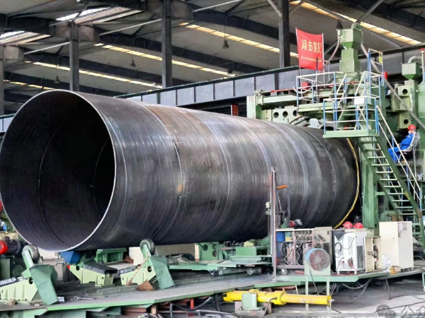
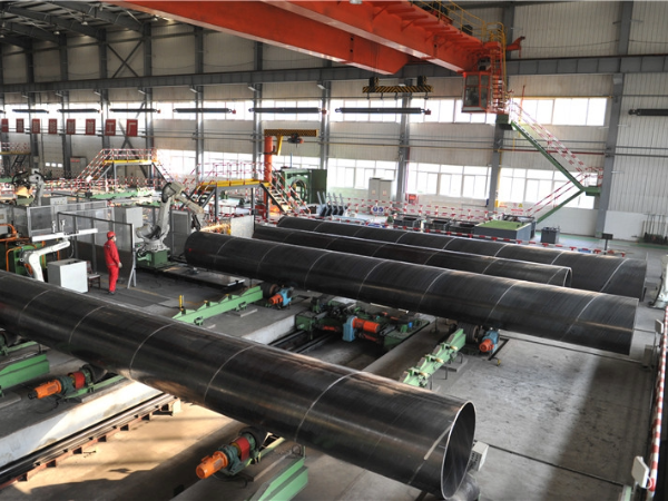
Spiral Welded Pipe production by submerged arc method is based on using tandem welding technique for joining inside and outside coil edges, which have been trimmed and beveled by carbide milling for high quality weld structure.
- Chemical Component Analysis
- Mechanical Properties
- Elongation, Yield Strength, Ultimate Tensile Strength
- Technical Properties
- DWT Test, Impact Test, Blow Test, Flattening Test
- X-Ray Test
- Exterior Size Inspection
- Hydrostatic Test
- UT Test
Frequently Asked Questions
1. How does spiral angle affect SSAW pipe performance?
The spiral angle (typically 30-60° per EN10219 Section 5.2) directly impacts pipe stress distribution:
Hoop stress carries primary internal pressure load per ASME B31.3 — longitudinal stress is reduced by sin²(α) factor where α = spiral angle.
Angle effect per API 5L Section 10.2.2:
(1) 30-40°: longitudinal stress = 25-41% of hoop — closer to LSAW performance
(2) 45°: balanced distribution for combined loading
(3) 50-60°: longitudinal stress = 59-75% of hoop — higher shear at weld
Formula per BS EN 1993-1-1: σ_long = σ_hoop × sin²(α). Smaller angles (30-40°) preferred for pressure > 6MPa per API 5L Table 6.
2. Why is SSAW not recommended for high-pressure pipelines?
Per ASME B31.3 Table A-1B, SSAW weld joint factor E = 0.85 vs E = 1.0 seamless and E = 0.95 LSAW — reducing allowable working pressure by 15%.
Additional code limits:
(1) API 5L Section 10.2.3.2: spiral weld DWT minimum shear area 85% for X65+ per Annex A
(2) DNV-OS-F101 Sec 5 Table 2-1: SSAW design factor ≤ 0.72 offshore vs 0.80 LSAW
(3) ISO 3183 Table 6: spiral weld reinforcement ≤ 2.0mm vs ≤ 1.5mm longitudinal
Pressure limits per ASME B31.4 Table 402.1: SSAW ≤ 8MPa at 1200mm OD × 14mm WT X52, LSAW ≤ 10.2MPa — 27.5% higher. SSAW ideal for water (≤1.6MPa per AWWA C200) and piling.
3. What are the cost advantages of large-diameter SSAW?
For OD > 1000mm per EN10219: SSAW coil-fed forming eliminates plate cutting ($12-18/m² per AWS D1.1 Section 5.15) and reduces edge prep time by 60%.
Cost factors per ISO 3183 Annex B:
(1) Material yield: coil width = π × OD × tan(90°-α) — 92-96% utilization vs 85-88% LSAW plate
(2) Speed: SSAW 10-15m/min vs LSAW JCOE 2-3m/min (per EN 1993-1-1)
(3) At OD 1420mm × WT 14mm X52: SSAW cost advantage 15-20%/ton — 40% lower labor/m + 8% better yield.
Per AWWA C200 Table 1: SSAW specified for water ≤ 2.5MPa where cost advantage > 20% at >1500mm OD.
4. How is spiral weld quality ensured in SSAW production?
Per AWS D1.1 Section 4.8 and API 5L Section 10.2.2:
Welding per ASME Section IX QW-409:
(1) Multi-wire SAW: 2-3 electrodes, current 600-1200A, voltage 28-36V, travel speed 0.8-1.5m/min
(2) Flux per ISO 14174: SA AB 1 (basic), recovery ≥ 98%
NDT per API 5L Section 10.2.5:
(1) 100% UT of weld seam per ASTM E164 — acceptance per API 5L Table 8 (max 12.5% wall loss)
(2) X-ray per ASTM E94: 100mm from each end per API 5L Table 9 (no linear indications ≥ 25mm PSL2)
(3) Strip edge offset: ≤ 1mm for ≤ 14mm WT, ≤ 1.5mm for > 14mm WT per API 5L Section 10.2.2.4
(4) Inter-pass temperature: ≤ 200°C per API 1104 Table 5
5. What is the difference between SSAW and HSAW?
Per API 5L 46th Edition Section 3.1 and ISO 3183: SSAW and HSAW are the same process — double-side SAW, continuous coil feed, 30-60° forming angle.
Key parameters:
(1) Forming angle: 30-60° relative to pipe axis per API 5L Section 5.2.1
(2) Strip width determines max OD — formula: OD_max = strip_width / (π × cos(α))
(3) Coil thickness range: 6-25mm per ISO 3183 Table 1
Production limits:
(1) Min OD: ~406mm (30° forming angle with 600mm strip per EN10219 Section 4.2)
(2) Max OD: ~2540mm (1500mm strip at 50°)
No quality difference — terms are interchangeable per API 5L Section 3.1.
6. How does SSAW handle wall thickness variation along the pipe?
SSAW uses single-coil thickness per pipe — wall thickness is uniform along length per API 5L Section 9.3:
(1) One coil = one wall thickness throughout pipe
(2) Coil edges trimmed before forming, not in final pipe per API 5L Section 7.3.2
(3) Weld reinforcement: 0-3mm controlled by SAW parameters per AWS D1.1 Section 4.10
Inspection per API 5L Section 10.2.5.3:
(1) UT wall thickness at 4 points/cross-section every meter per ASTM E213
(2) End measurement at both pipe ends per API 5L Section 9.6
(3) Ovality per Table 9: ≤ 2.0% of OD for SSAW
For tapered wall (variable thickness) applications, LSAW with precision-machined plate per API 5L Annex F is required.