
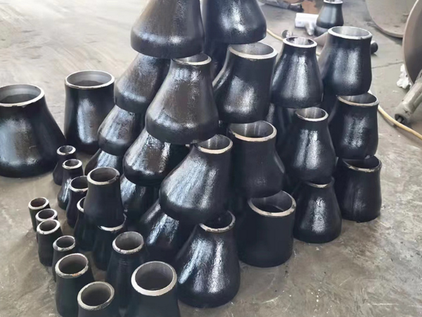
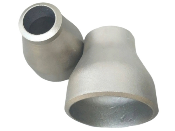
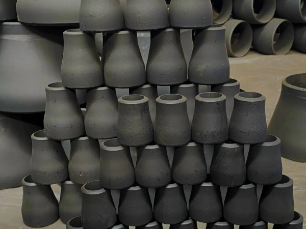
| Reducer Type | Concentric Reducer, Eccentric Reducer |
| Material | Carbon Steel --- ASTM A234 WPB/WPC, ASTM A105/A106/A53/A283-D, |
| API 5l GR.B/A671-CC-70/A515-50/A135-A/A179-C | |
| ASTM 403 304/304L, 316/316L,316Ti,321,317L,310S | |
| Alloy Steel --- ASTM 234 WP 1/5/9/11/12/22/91 | |
| Specification | Alloy Steel --- ASTM 234 WP 1/5/9/11/12/22/91 |
| WT: 2-80mm, SCH 40/80/XXS | |
| Surface | Light Oiling, Black Painting |
| Packing | Packed in Wood Cabins/ Wood Tray |
pipe fitting reducer Introduction
Reducer Type
Concentric Reducer, Eccentric Reducer
Material
Carbon Steel --- ASTM A234 WPB/WPC, ASTM A105/A106/A53/A283-D,
Stainless Steel --- ASTM 403 304/304L,316/316L,316Ti,321,317L,310S
Alloy Steel --- ASTM 234 WP 1/5/9/11/12/22/91
Specification
NPS from 3/4" to 48", DN from 20 to 1200
WT 2-80mm, SCH 40/80/XXS
Surface
Light Oiling, Black Painting
Packing
Packed in Wood Cabins/ Wood Tray
API 5l GR.B/A671-CC-70/A515-50/A135-A/A179-C
Specification of Steel Pipe Reducer
|
Nominal Pipe Size |
1/2-1½ |
3-3½ |
4 |
5-8 |
10-18 |
20-24 |
26-30 |
32-48 |
|
Outside Diameter at Bevel(D) |
+1.6 -0.8 |
1.6 |
1.6 |
+2.4 -1.6 |
+4 -3.2 |
+6.4 -4.8 |
+6.4 -4.8 |
+6.4 -4.8 |
|
Inside Diameter at End |
0.8 |
1.6 |
1.6 |
1.6 |
3.2 |
4.8 |
+6.4 -4.8 |
+6.4 -4.8 |
|
Overall Length(H) |
2 |
2 |
2 |
2 |
2 |
2 |
5 |
5 |
|
Wall Thickness(T) |
Not less than 87.5% of Nominal Wall Thickness |
|||||||
Applications of Steel Pipe Reducer:
Hydraulic system
Pneumatic system
Pharmaceutical fittings
Air brake fittings
Gas fittings
Refrigerant fittings
Material & Standard of Steel Tube Reducer:
Carbon Steel --- ASTM A234 WPB/WPC, ASTM A105/A106/A53/A283-D, API 5l GR.B/A671-CC-70/A515-50/A135-A/A179-C;
Stainless Steel --- ASTM 403 304/304L, 316/316L,316Ti,321,317L,310S;
Alloy Steel --- ASTM 234 WP 1/5/9/11/12/22/91
Ends of Pipe Reducer:
Square Ends/Plain Ends (straight cut, saw cut, torch cut), Beveled/Threaded Ends
Penetrant Testing:
Penetrant solution is applied to pipe fittings or flanges cleaned surfaces.The liquid is pulled into cracks or defects by capillary action.Excess penetrant material is carefully cleaned from the surface.A developer is applied to pull the trapped penetrant material back to the surface where it is spread out and shows an indication.This indication is much easier to find than the crack or defect.
Magnetic Particle Testing
A magnetic field is established in a pipe fitting made from ferromagnetic material.The magnetic lines of force travel through,exit and reenter the material at the poles.Defects such as crack or voids cannot support as much flux,and force some of the flux outside of the part.Magnetic particles distributed over this pipe fitting will be attracted to areas of flux leakage and shows a visible indication.
Ultrasonic Testing
When the quality checker use a transducer to send the high frequency sound waves to a pipe fitting or flange.The waves travel through the product and are received by the same transducer or another one.The amount of energy transmitted or received and the time of the energy is received are analyzed to determine the presence of flaws.Changes in material thickness and properties could be measured too.
Eddy Current Testing
The Eddy current testing is used a lot as the NDT method for seamless steel pipes.Alternating electrical current is passed through a steel pipe producing a magnetic field.When the pipe is placed closed to a conductive material,the changing magnetic field induces current flow in the pipe.These currents travel in closed loops and are called eddy currents.Eddy currents produce their own magnetic field that can be measured and used to find flaws.
Radiographic Testing
Our QC team use RT to check the quality of welded seam.They put the radiation source and detector on the two sides of the seam,and use X-ray to produce images of welded seam from film or other detector that is sensitive to radiation.The thickness and density of the welded seam that X-rays must penetrate affects the amount of radiation reaching the detector.This variation in radiation produces an image on the detector that often shows internal features of the test seam.
|
NOMINAL PIPE SIZE NPS |
ANGULARITY TOLERANCES |
ANGULARITY TOLERANCES |
ALL DIMENSIONS ARE GIVEN IN INCHES. TOLERANCES ARE EQUAL PLUS AND MINUS EXCEPT AS NOTED. |
|
|
Off Angle Q |
Off Plane P |
(1) Out-of-round is the sum of absolute values of plus and minus tolerance. |
|
½ to 4 |
0.03 |
0.06 |
|
|
5 to 8 |
0.06 |
0.12 |
|
|
10 to 12 |
0.09 |
0.19 |
|
|
14 to 16 |
0.09 |
0.25 |
|
|
18 to 24 |
0.12 |
0.38 |
|
|
26 to 30 |
0.19 |
0.38 |
|
|
32 to 42 |
0.19 |
0.50 |
|
|
44 to 48 |
0.18 |
0.75 |
Concentric Reducer: Symmetrical cone shape with centerline alignment. Ideal for vertical pipelines, pump suction lines, and applications requiring smooth velocity transitions. Maintains uniform flow distribution without stratification. Standard choice for steam, gas, and vertical liquid transport.
Eccentric Reducer: Features offset centerline with one flat side. Flat-side-up configuration prevents vapor binding in gas service and promotes unobstructed flow. Flat-side-down orientation eliminates liquid pockets in drainage and condensate removal systems. Essential for horizontal pipeline networks handling multi-phase fluids.
Butt Weld Reducers: NPS 1/2 to NPS 60 (DN15 to DN1500) per ASME B16.9. The dominant choice for high-pressure hydrocarbon service, steam systems, and critical process pipelines requiring leak-tight welded joints.
Threaded Reducers: NPS 1/8 to NPS 4 (DN6 to DN100) per ASME B16.11. Limited to low-pressure utility systems, instrumentation, and applications where welded connections are impractical.
Socket Weld Reducers: NPS 1/8 to NPS 2 (DN6 to DN50) per ASME B16.11. Designed for small-bore instrumentation, gauge connections, and process sampling systems.
Swage Reducers (Threaded or Butt Weld): NPS 1/8 to NPS 12 for rapid diameter transitions in confined spaces. Economical solution for temporary or adjustable pipeline configurations.
ASME B16.9 Schedules: Schedule 10 through XXS provide matching pressure containment to corresponding pipe wall thicknesses. Rating determined by ASME B31.3 or B31.1 pressure-temperature tables at operating temperature.
MSS SP-75 WHP Classes: Class 35 (2,420 psi at 100°F), Class 46 (3,000 psi), Class 50 (3,750 psi) offer enhanced pressure capability for equivalent wall thickness. Standard for high-pressure gas transmission and refining applications.
Temperature Limits: Carbon steel (-20°F to 800°F), Stainless steel 304/316 (-425°F to 1,500°F), Duplex stainless (-50°F to 600°F). Always verify rating reduction factors at elevated temperatures per applicable code.
Carbon Steel: ASTM A234 WPB (general service, -20°F to 800°F), WPC (elevated temperature to 850°F), WPL6/WPL9 (low-temperature to -75°F). WPHY 42/46/52/60/65 for pipeline transmission systems requiring Charpy impact testing.
Stainless Steel: Type 304/304L (general corrosion resistance), Type 316/316L (chloride pitting resistance for coastal/marine environments), Type 321 (stabilized for welding and elevated temperature), Type 310S (thermal cycling applications to 2,100°F).
Alloy Steel: WP11 (1.25Cr-Mo for petroleum refining), WP22 (2.25Cr-Mo for hydrocracker and delayed coker units), WP9/WP91/WP92 (creep-resistant grades for power generation and reformer services).
Duplex/Super Duplex: UNS S31803 (2205, 65,000 psi yield strength) and UNS S32750 (2507, 80,000 psi yield strength) for sour service, seawater cooling systems, and chloride-rich process streams. PREN rating of 35+ provides superior pitting and stress corrosion cracking resistance.
K-Value Method: Use Crane Technical Paper 410 for loss coefficients. Expansion (K = 1.0 - (D2/D1)²) and contraction (K = 0.5(1 - (D2/D1)²)) calculations determine head loss. K-value multiplied by velocity head (V²/2g) equals pressure drop.
Diameter Ratio Impact: Large reductions (D1/D2 > 2.0) significantly increase turbulence and separation losses. Consider two-step reduction for ratio exceeding 3:1 to minimize total pressure loss.
Radius Selection: Long-radius (L/D = 1.0 for each end) reduces pressure drop by 30-50% versus short-radius (L/D = 0.5). Standard radius per ASME B16.9 provides acceptable performance for most applications.
Flow Regime Consideration: Reynolds number affects K-value accuracy. Below Re = 3,000 (laminar flow), viscosity effects dominate. Above Re = 10,000 (turbulent flow), standard K-values apply. Consult Crane TP-410 for detailed guidance.
Butt Weld Preparation: Bevel angle per ASME B16.25 (30°±5° for standard wall). Internal/external weld dimensions must ensure complete penetration without overlap. Post-weld heat treatment mandatory for P1 and P3 materials when specified by design code.
Alignment and Fit-Up: Maximum offset limited to 1/16 inch per ASME B16.9 tolerances. Excessive mismatch creates turbulence, erosion, and potential fatigue failure at welds. Use line-up clamps for diameters exceeding NPS 6.
Eccentric Orientation: Verify installation drawing for required orientation. Incorrect positioning creates flow disturbances, pocket formation, or vapor binding. Mark orientation on outside of fitting before lowering into trench or placing in rack.
Quality Documentation: EN 10204 3.1 mill test certificates mandatory including heat chemistry, tensile properties, hardness values, and heat treatment condition. NDE reports (PT, MT, RT, UT) available upon request. Third-party inspection (SGS, Bureau Veritas, DNV) available for critical applications.