
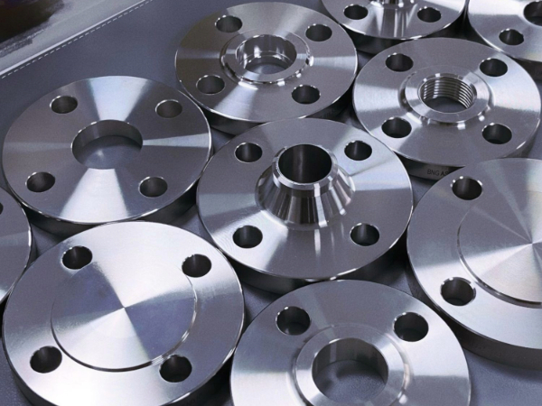
| Size: | OD: DN15- DN2000 (1/2''- 80'') |
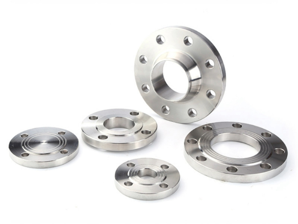
| Type: welding neck, slip on, blind, socket welding, threaded, lap-joint | |
| Pressure: 150#, 300#, 600#,900#,1500#, 2500# | |
| Material: | carbon steel A105, C22.8, S235, S235JR, P235GH,SS400,37.2 |
| Stainless Steel 304/L,316/L,321,310S,347H,1.4301, 1.4404 | |
| ASTM A234 WP1/5/9/11/12/22/91 | |
| Duplex stainless steel: UNS31803, SAF2205, UNS32205, UNS31500 | |
| Coating: | Rust-proof oil, cold and hot galvanize |
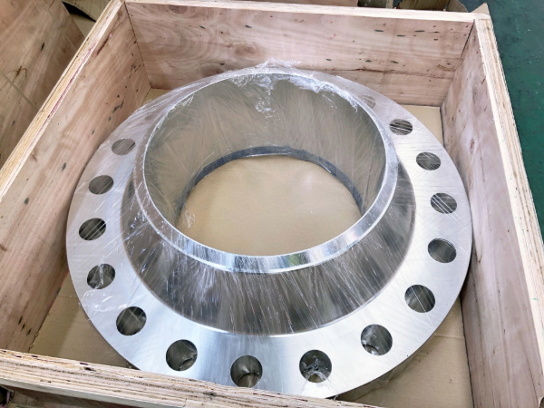
| Packing | sea worthy plywooden case, wooden pallet |
Pipe Fitting Flange Introduction
Size:
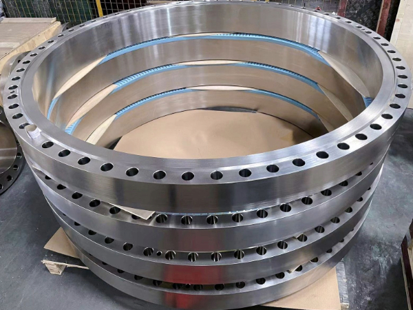
OD: DN15- DN2000 (1/2"- 80")
Type: welding neck, slip on, blind, socket welding, threaded, lap-joint
Pressure: 150#, 300#, 600#,900#,1500#, 2500#
Material:
carbon steel A105, C22.8, S235, S235JR, P235GH,SS400,37.2
Stainless Steel 304/L,316/L,321,310S,347H,1.4301, 1.4404
ASTM A234 WP1/5/9/11/12/22/91
Duplex stainless steel: UNS31803, SAF2205, UNS32205, UNS31500
Coating:
Rust-proof oil, cold and hot galvanize
Packing
sea worthy plywooden case, wooden pallet
Size:
OD: DN15- DN2000 (1/2"- 80")
Common Steel Tube Flange Types:
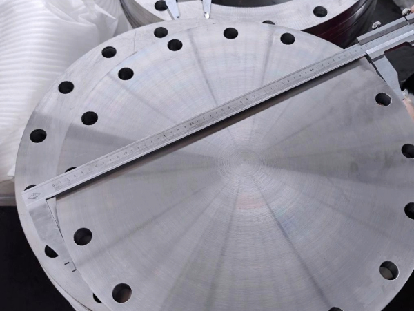
Blind flange
Weld neck flange
Socket weld flange
Slip on flange
Thread flange
Raised Face Flange
Lap Joint Flange
Blind flange
|
Product Name: |
Blind flange |
|
Material: |
Carbon Steel Flange: 20#, Q235, A105, Stainless Steel Flange: F304 F304L |
|
Surface Treatment: |
Anti-rust Oil, Transparent / Yellow / Black Anti-rust Paint, Zinc / Hot dipped Galvanized |
|
Size: |
15A- 2000A, 1/2"-78" |
|
Class: |
Class400, Class600, Class900, Class1500, Class2500 |
Weld neck flange
|
Product Name: |
Weld neck flange |
|
Material: |
Stainless steel, Carbon steel, Alloy steel |
|
Standard: |
ASTM, ASME, JIS, DIN, BS |
|
Size: |
1/2 - 24" |
|
Class: |
Class150, Class300, Class400, Class600, Class900, Class1500, Class2500 |
Socket weld flange
|
Product Name: |
Socket weld flange |
|
Material: |
Stainless steel, Carbon steel, Alloy steel |
|
Standard: |
ASTM, ASME, JIS, DIN, GB, BS |
|
Size: |
1/2 - 24" |
|
Class: |
Class150, Class300, Class400, Class600, Class900, Class1500, Class2500 |
Slip on flanges
|
Product Name: |
Slip On Flange |
|
Material: |
Carbon Steel Flange: 20#, Q235, |
|
Standard: |
ASTM, ASME, JIS, DIN, GB, BS |
|
Size: |
15A- 2000A, 1/2"-78" |
|
Class: |
Class150, Class300, Class400, Class600, Class900, Class1500, Class2500 |
Threaded flange
|
Product Name: |
Threaded flange |
|
Material: |
Stainless steel, Carbon steel, Alloy steel, Nickel alloy, Copper alloy, Copper, Brass and Bronze |
|
Standard: |
ASTM, ASME, JIS, DIN, GB, BS |
|
Size: |
1/2"NB TO 60"NB IN |
|
Class: |
Class150, Class300, Class400, Class600, Class900, Class1500, Class2500 |
Lap joint flange
A lap joint flange, abbreviated as LJF, is a flange that consists of two parts, a stub end and the backing flange.
In general, the thickness of the hub is between ¼" to 3/8".
Raised face flange
the most common type of flange facing is the raised face flange, abbreviated as RF. It is used in almost all applications in high and low pressures and temperatures.
The face of the flange is either 1/16" or 1/4" depending on the pressure class. ANSI 300 and under have a 1/16" raised face and ANSI 400 and above have a 1/4" raised face.
Blind flange Weld neck flange Socket weld flange Slip on flange Thread flange
Raised Face Flange Lap Joint Flange
Hydrostatic Test
. Not required unless specifically requested by purchaser
. Code mandate that flange shall be able to withstand under pressure test of rating of finished part.
Non Destructive Testing
. Ultrasonic test
. Magnetic particle test o Liquid penetrant test
. Positive Material Identification
Destractive Testing
. Tensile test
. Hardness test
. Impact test / Charpy V-Notch Test
Metallurgical Test
Chemical Analysis of -Raw material -Product ·Special test
. Grain size (AS & SS)
. IGC- Intergranular Corrosion Test(SS) -Ferrite (SS)
. HIC- Hydrogen-induced Cracking
. SSC- Sulfide Stress Corrosion Cracking
Visual Inspection
. Check for any surface imperfection and overall product quality
. Check for unfinished machine surface
. Check for any serration damage on flange face
. Being a machined product no surface defect is acceptable.
Steel Pipe Flange Dimensional Tolerances
This table displays Flange Dimensional Tolerances by inside, outside, and contact diameter, thickness, and drilling tolerances for bolt holes diameter and spacing. These standard flange dimensional tolerances are ideal when other specifications aren't used.
|
OUTSIDE DIAMETER |
When O.D. is 24" or less |
+0.125" , -0.0625" |
|
When O.D. over is 24" |
+0.125" , -0.125" |
|
|
INSIDE DIAMETER |
When I.D. is 10" or less |
+0.03125" , -0" |
|
When I.D. over is 10" |
+0.0625" , -0" |
|
|
CONTACT FACE DIAMETER |
Raised Face |
+0.0156" , -0.0156" |
|
DRILLING |
Bolt Hole Diameter |
+0.03125" , -0.03125" |
|
Bolt Circle Diameter |
+0.0625" , -0.0625" |
|
|
Bolt Hole Spacing |
+0.03125" , -0.03125" |
|
|
THICKNESS |
When nominal size is 18" or less |
+0.125" , -0 |
|
When nominal size is over 18" |
+0.1875" , -0 |
Chemical Composition (%) of ASTM A234/A234M
|
Grade |
Type |
C |
Si |
S |
P |
Mn |
Cr |
Ni |
Mo |
Other |
σb |
σs |
d5 |
|
WPB |
0 |
0.1min |
0.058 |
0.05 |
0.29-1.06 |
0.4 |
0.4 |
0.15 |
V:0.06;Nb:0.02 |
415-585 |
240 |
22 |
197 |
|
WPC |
0.35 |
0.1min |
0.058 |
0.05 |
0.29-1.06 |
0.4 |
0.4 |
0.15 |
V:0.06;Nb:0.02 |
485-655 |
275 |
22 |
197 |
|
WP1 |
0.28 |
0.1-0.5 |
0.045 |
0.045 |
0.3-0.9 |
|
|
0.44-0.65 |
|
380-550 |
205 |
22 |
197 |
|
WP12 CL1 |
0.05-0.2 |
0.6 |
0.045 |
0.045 |
0.3-0.8 |
0.8-1.25 |
|
0.44-0.65 |
|
415-585 |
220 |
22 |
197 |
|
WP12 CL2 |
0.05-0.2 |
0.6 |
0.045 |
0.045 |
0.3-0.8 |
0.8-1.25 |
|
0.44-0.65 |
|
485-655 |
275 |
22 |
197 |
|
WP11 CL1 |
0.05-0.15 |
0.5-1 |
0.03 |
0.03 |
0.3-0.6 |
1-1.5 |
|
0.44-0.65 |
|
415-585 |
205 |
22 |
197 |
|
WP11 CL2 |
0.05-0.2 |
0.5-1 |
0.04 |
0.04 |
0.3-0.8 |
1-1.5 |
|
0.44-0.65 |
|
485-655 |
275 |
22 |
197 |
|
WP11 CL3 |
0.05-0.2 |
0.5-1 |
0.04 |
0.04 |
0.3-0.8 |
1-1.5 |
|
0.44-0.65 |
|
520-690 |
310 |
22 |
197 |
|
WP22 CL1 |
0.05-0.15 |
0.5 |
0.04 |
0.04 |
0.3-0.6 |
1.9-2.6 |
|
0.87-1.13 |
|
415-585 |
205 |
22 |
197 |
|
WP22 CL3 |
0.05-0.15 |
0.5 |
0.04 |
0.04 |
0.3-0.6 |
1.9-2.6 |
|
0.87-1.13 |
|
520-690 |
310 |
22 |
197 |
|
WP5 CL1 |
0.15 |
0.5 |
0.03 |
0.04 |
0.3-0.6 |
4-6 |
|
0.44-0.65 |
|
415-585 |
205 |
22 |
217 |
|
WP5 CL3 |
0.15 |
0.5 |
0.03 |
0.04 |
0.3-0.6 |
4-6 |
|
0.44-0.65 |
|
520-690 |
310 |
22 |
217 |
|
WP9 CL1 |
0.15 |
1 |
0.03 |
0.03 |
0.3-0.6 |
8-10 |
|
0.9-1.1 |
|
415-585 |
205 |
22 |
217 |
|
WP9 CL3 |
0.15 |
1 |
0.03 |
0.03 |
0.3-0.6 |
8-10 |
|
0.9-1.1 |
|
520-690 |
310 |
22 |
217 |
|
WPR |
0.2 |
|
0.05 |
0.045 |
0.4-1.06 |
|
1.6-2.24 |
|
|
435-605 |
315 |
22/28 |
217 |
|
WP91 |
0.08-0.12 |
0.2-0.5 |
0.01 |
0.02 |
0.3-0.6 |
8-9.5 |
0.4 |
0.85-1.05 |
See sdandard |
585-760 |
415 |
20 |
248 |
|
WP911 |
0.09-0.13 |
0.1-0.5 |
0.01 |
0.02 |
0.3-0.6 |
8.5-10.5 |
0.4 |
0.9-1.1 |
See sdandard |
620-840 |
440 |
20 |
248 |
Notes:
For each reduction of 0.01% below the specified C maximum, an increase of 0.06% Mn above the specified maximum will be permitted, up to a maximum of 1.35%.
The sum of Cu, Ni, Cr, and Mo shall not exceed 1.00%.
The sum of Cr and Mo shall not exceed 0.32%.
The maximum carbon equivalent (C.E.) shall be 0.50, based on heat analysis and the formula C.E.=C+Mn/6+(Cr+Mo+V)/5+(Ni+Cu)/15.
Weld Neck Flanges (WN): Feature long tapered hub transitioning to pipe OD with full bevelled butt weld preparation. Hub reinforcement provides fatigue resistance 3x higher than slip-on equivalents. Mandatory for ASME B31.3 Category M fluid service, high-pressure gas transmission, and cyclic loading applications. Standard for refinery cat cracker regenerator and reactor inlet/outlet piping.
Blind Flanges (BL): Solid radial through-bore configuration with boltholes. Pressure-containing closure for vessel nozzles, manways, and pipe terminations. Pressure-temperature ratings identical to companion flanges at matched class. Calculate required bolting torque using API 6A/6B gasket stress formulas considering combined hydrostatic end force and gasket preload requirements.
Slip-On Flanges (SO): Bore slightly larger than pipe OD; circumferential Fillet weld inside and outside hub. Hub wall reinforcement acceptable for Class 150/300 at ambient temperature. Maximum allowable pressure per ASME B16.5 Table 2 limited to 85% of comparable WN rating. Prohibited in API 610 pump suction and high-vibration service due to fatigue vulnerability.
Socket Weld Flanges (SW): Internal socket bore accepts pipe to contact shoulder; single external fillet weld. Limited to NPS 1/2 through NPS 2 per ASME B16.11 due to strength concerns. Restrict to clean, non-corrosive service; water treatment and instrument air applications only. Not permitted for cyclic thermal service causing differential expansion.
Threaded Flanges (TH): Internal NPS thread profile matches API modified thread form per ASME B1.20.1. Single external hub fillet weld required for pressure integrity above Class 300. Economic choice for temporary connections, laboratory systems, and locations prohibiting hot work. Sealing compounds (PTFE tape, anaerobic sealants) mandatory for leak-tight joint.
Lap Joint Flanges (LJ): Collapsible design with backing flange and lapped stub end fusion welded to pipe. Backing flange rotates freely for bolt hole alignment; hub does not contain pressure. Ideal for systems requiring frequent disassembly: filter housings, exchanger channels, sampling systems. Stub end material may differ from backing flange for cost optimization.
ASME B16.5 Rating Basis: Pressure-temperature ratings establish maximum allowable working pressure (MAWP) at specified temperature. Ratings inversely proportional to temperature; higher temperature reduces allowable pressure due to material strength degradation. Ratings apply to flange materials only; gaskets and bolting have independent temperature limits.
Class Selection Criteria: Base selection on system design pressure plus 10% margin minimum. For hydrostatic test pressure (1.5x design), flanges must resist without visible leakage. Consider water hammer and pressure spikes; specify one class higher if transient events exceed 25% of design pressure.
Temperature Restrictions: Carbon steel (A105) ratings valid from -29°C to 425°C. Below -29°C, specify ASTM A350 LF2 with impact testing mandatory. Stainless steel (F304) retains strength to 800°C but NACE MR0175/ISO 15156 restrictions apply in H₂S service. Verify flange temperature matches pipe temperature including solar radiation effects in outdoor installations.
Series B vs Series A: ASME B16.47 Series A (MSS SP-44 heritage) bolt hole patterns differ from Series B (API 605). Series A compatible with ASME B16.5 bolt circles; Series B not interchangeable. Specify series explicitly to avoid field fit-up problems with NPS 26-60 flanges.
Carbon Steel ASTM A105: Primary material for WN and blind flanges NPS 1/2 through NPS 24. Yield strength 36,000 psi; tensile 70,000-85,000 psi. Maximum carbon content 0.35% limits hardenability; not subject to post-weld heat treatment unless specified. Suitable for ASTM A216 WCB cast equivalents in Class 150/300 service.
Low-Temperature Service: ASTM A350 LF2 Class 1 mandatory below -29°C with Charpy V-notch impact requirements. CTOD considerations for offshore platform topside piping below -20°C. A350 LF3 (3.5% Ni) for cryogenic service to -170°F in LNG storage and vaporization facilities.
Stainless Steel ASTM A182: F304/F304L (18Cr-8Ni) for general corrosion service; dual-certified 304/304L preferred for welded construction. F316/F316L (16Cr-12Ni-2Mo) for chloride-containing environments; 2% molybdenum provides pitting resistance equivalent (PRE) >28. F321 stabilized (Ti addition) prevents sensitization in welded assemblies operating 425-900°C. F310S (25Cr-20Ni) for high-temperature to 2,100°F in fired heater applications.
Alloy Steel ASTM A182: F11 (1.25Cr-0.5Mo) and F22 (2.25Cr-1Mo) for refinery hydrocracker and delayed coker service to 1,000°F. PWHT mandatory per ASME B16.5 Note 5 when wall exceeds schedule 80. F91/F92 (9Cr-1Mo-V) for ultra-supercritical power generation at 1,050°F with enhanced creep rupture strength.
Duplex Stainless A182 F51/F53: UNS S31803 (2205) provides 2x yield strength versus austenitic grades with PREN >35. UNS S32750 (2507) PREN >40 for seawater cooling and desalination. Mandatory solution anneal + quench practice; sensitization from improper heat treatment causes catastrophic brittle failure.
Raised Face (RF) Flanges: 1/16 inch (1.6mm) concentric raised face standard per ASME B16.5. Spiral wound gaskets with inner/outer rings (SW + IOR) recommended for Class 150-2500. Compressed non-asbestos fiber (CNAF) gaskets for Class 150-300 water and steam service. Skive-cut PTFE gaskets for chemical processing with aggressive media. Bolt stress 35,000-50,000 psi typical; torque values per ASME PCC-1 Appendix J.
Flat Face (FF) Flanges: Full face contact with compressible gasket. Full face rubber gaskets (EPDM, NBR) for Class 125/250 cast iron flanges in water distribution. Fiberglass-reinforced phenolic for Class 300+ steel flat face flanges. Gasket factor m = 2.0,-y = 1,800 psi per ASME Section VIII. Contact stress uniformity critical; flange warp tolerance 0.002 inch maximum.
Ring Type Joint (RTJ) Flanges: Octagonal cross-section RTJ groove standard; oval RTJ acceptable for Class 75/150 only. Soft iron RTJ for temperatures to 530°C; 316 stainless RTJ for corrosion service. API 601 stainless steel jacketed gaskets for 316L wetted parts. Flange facing finish Ra 125-250 μin required; spiral finish prohibited. Spiral finish grooves create gasket extrusion path under compression.
Male-Female and Tongue-Groove: ASME B16.5 permits but does not specify gasket types. Male-female suitable for caulked lead gaskets in low-pressure steam. Tongue-groove limited to Class 300-600 with spiral wound gaskets. Not recommended for flange classes above 600 due to stress concentration at groove root.
Bolting Area Calculation: Required bolt load = pressure load (Aᵢ × P) + gasket seating load (G × y). Available bolt area = Σ(bolt tensile stress area × number of bolts). Design margin: available/required ≥ 1.0; recommended 1.2-1.5 for thermal cycling service.
ASTM A193 B7 Bolts: Most common bolting for Class 150-600 steel flanges. Tensile 125,000 psi; yield 105,000 psi at -20°F to 800°F. Specify A194 Grade 2H nuts for B7 companion. Hydrostatic test condition requires bolt preload 1.2x operating load; cold gastight test requires 1.5x operating.
ASME PCC-1 Torque Procedure: Calculate target bolt stress based on gasket parameters. Apply lubricant (k = 0.15 coefficient) to both nut bearing surfaces. Final torque = 1.25x skidproof torque; skidproof torque = target stress × bolt root area × 0.2 / nut radius. Skidproof torque compensates for bolt stretch during initial tightening.
Leak Prevention: Gasket stress relaxation occurs under sustained load; retorque Class 150 ANSI flanges after 24-48 hours. Spiral wound gaskets with IOR require seating stress maintained above 10,000 psi minimum. PTFE envelope gaskets require compressive stress 4,000-8,000 psi; excessive torque causes rupture.
Flange Rotation Check: After assembly, apply flange rotation test per API 601: no visible flange gap when flange face pried. Rotation indicates insufficient gasket compression; retighten uniformly in star pattern. Exposed gasket edges after hydrotest indicate inadequate seating stress.
Material Test Reports (MTR): EN 10204 3.1 mandatory for each heat number. Heat chemistry including residual elements (S ≤ 0.040%, P ≤ 0.045% for A105). Mechanical properties: tensile, yield, elongation, reduction of area. Hardness verification ≤ 187 HBW for A105; ≤ 201 HBW for stainless.
Dimensional Verification: Per ASME B16.5 Tables 1-5 tolerances. Bolt circle diameter tolerance ±0.031 inch; bolt hole diameter tolerance +0.031/-0.000 inch. Flange OD tolerance varies by class: Class 150 ±0.0625 inch typical. Raised face height 1/16 inch ±1/32 inch.
Non-Destructive Examination: Visual examination per ASME A960: no cracks, laps, seams, or other injurious defects. Liquid penetrant examination (LPE) for NPS <24 when specified for Category D fluid service. Magnetic particle examination (MPE) for ferromagnetic materials alternative to LPE. Hydrostatic test: 1.5x MAWP minimum; hold 5 minutes; no visible leakage.
Third-Party Inspection (TPI): DNV, Bureau Veritas, SGS for critical offshore and subsea applications. API 600, API 602, API 6D compliance verification. Witness material testing, dimensional inspection, and hydrostatic testing. Documentation package: MTR, DII, NDE reports, hydrostatic test certificates, material traceability records.