
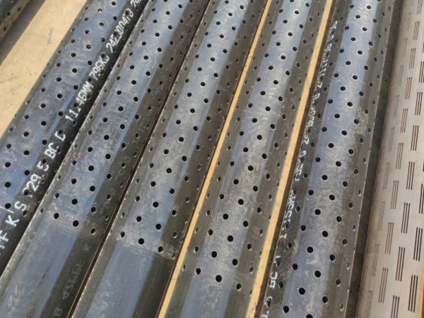
Screen Pipe Standard:
API 5CT, API 5L, ASTM, JIS
Screen Pipe Application:
Municipal water source well
Domestic well
Agricultural water well
Groundwater
Screen Pipe Tape and Advantages:
Different geological environment causes Screen Pipes with different grade and type, including Slotted Screen Pipe, Perforated Screen Pipe, Premium Mesh Sand Screens, Pre Packed Well Screen, Wire Wrapped Screen, Bridge Slotted Screen, Metal Mesh Sand Screen, etc.
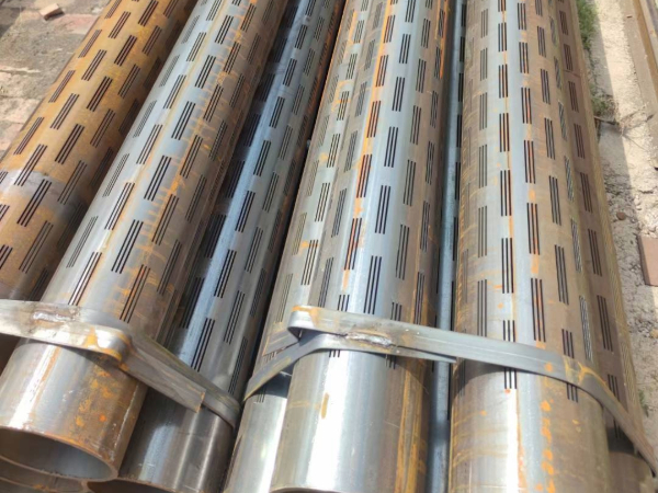
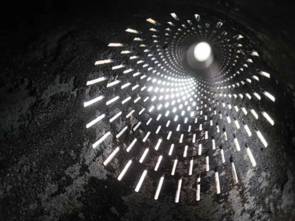
Slotted Liner
The slotted liner is mainly used to the water and oil reservation layer without much sand. It's function is prevent rock bits dripping into the well bore. The working principle is allowing the certain size and coming through the surface with crude oil but keeping the bigger size sand stopped outside to form sand bridge, and thereby achievement the anti-sand purpose. This type of produce is commonly used to sand rock and catbonate reservoir and especially useable for horizontal wells.
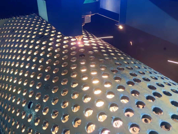
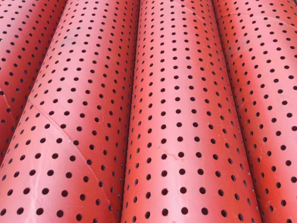
Perforated pipe
Carbon steel perforated pipes manufactured with carbon steel or stainless steel. We can drill standard or customized hole size in any number and any pattern. Every joint perforated by us is deburred internal and external. Every hole is visually inspected and cleaned of burr material.
Bridge Slotted Screen pipe
Bridge slotted screen pipe is a new product which is composed of central tube, precise punched slotted screen jacket and stainless steel ring. It has characteristics such as exquisite controlled hole. High percentage of open area, strong integral strength, resistant to deformation to corrosion and high reliability etc.
Wedge Wire Water Screen Pipe
Wedge wire water screen pipe can be made single layer or double layers. The single layer can b cut to many kinds of sieve plate. The Sieve plate mainly used for water treatment and paper making industry.
Resistant to corrosion.
Sufficient column and collapse strength.
Well prevention of sand and grit.
Suitable for different geological environment with different type screens.
Improve well productivity and efficiency.
Slotting or perforation size can be customized.
Screen Pipe Specification:
|
Wire Size |
Width(mm): 1.50 1.80 2.30 3.00 3.30 3.70 |
|
Support Rods |
Width(mm): 2.30 3.00 3.30 3.70 |
|
Note: other wires and rods available upon request |
|
|
Slot size |
0.10, 0.15, 0.20, 0.25, 0.30 × 6.00mm also achieved upon request. |
|
Material: |
Low carbon steel, low carbon galvanized steel (LCG), stainless steel (304,316 etc.) |
|
Length |
Lengths up to 6 meters. |
|
Diameter |
Ranging from 25mm to 800mm. |
|
End connection |
Plain beveled ends for butt welding or threaded |
Wire wound screens feature continuously wound V-profile wire at 60-90° lay angle around longitudinal support rods. Wire cross-section ranges from 1.5×1.5mm to 4×4mm, with slot tolerances maintained at ±0.05mm via precision forming dies. The V-profile creates continuous slot geometry with open area 2-3× higher than bridge slotted alternatives.
Bridge slotted screens employ flat bar stock (typically 4-8mm thickness) with mechanically slotted openings. Bridge geometry provides superior collapse strength under external hydraulic pressure—critical for screen-only completions without gravel pack support. Collapse ratings reach 25-35 MPa for heavy-duty bridge slotted versus 15-20 MPa for equivalent wire wound in comparable OD.
Application matrix: Water wells with natural gravel pack—wire wound preferred for higher specific capacity (m³/hr per meter of drawdown). Unconsolidated formations with heavy sand content—bridge slotted offers superior slot integrity under abrasive particle movement. Geothermal wells with thermal cycling—wire wound accommodates differential thermal expansion without fatigue cracking at wire-to-rod welds.
Slot size determination follows API 11D1 and AWWA A100 laboratory sieve analysis procedures. Sieve fractions require reporting as d₁₀, d₅₀, d₆₀, and d₈₄ values with corresponding weight percentages. Uniformity coefficient (d₆₀/d₁₀) above 3 indicates well-graded formation requiring careful slot-to-formation bridging.
Recommended slot-opening-to-formation-size ratios: For gravel-packed completions, select slot width equal to 6-8× d₁₀ of gravel pack material. For natural pack completions, slot opening equals 1.5-2× d₅₀ of formation sand, ensuring bridge formation at individual sand grain contacts.
Slot tolerances: Wire wound ±0.05mm for slots 0.25-0.50mm; ±0.10mm for slots 0.50-2.0mm. Bridge slotted ±0.15mm regardless of slot width. Verify slot uniformity via 100% gauge pass/fail inspection on each screen joint.
API connections per API 5B: STC (Short Thread Coupling) provides economic solution for standard completion pressures. Thread form: 10 threads/inch (1.5-4.5"), 8 threads/inch (5-9.625"), 5 threads/inch (10.75-18.625"). Makeup torque ranges 1,500-8,000 ft-lb depending on size and weight.
API BTC (Buttress Thread): Modified thread form with asymmetric profile optimized for tension loading from pipe weight and thermal expansion. Standard for oilfield completions with pressure ratings 5,000-10,000 psi WP. Critical clearance at box nose prevents pressure-induced seal damage during makeup.
API LTC (Long Thread Coupling): Extended thread engagement (1.5× STC length) provides 25% higher tensile rating than STC at equivalent size/weight. Preferred for deviated wells with axial tension from dogleg severity. Seal integrity maintained through modified crest/trough interference fit.
Premium connections: TiWZ (Threaded-and-Welded Zone) combines threaded seal with circumferential weld reinforcement for H₂S service exceeding 15% partial pressure. Weld overlay on internal OD provides corrosion allowance in flow-wetted areas.
Carbon steel (J55, N80, L80 Type 1): Cost-effective baseline for sweet service wells with CO₂ partial pressure below 0.5 psi and absence of H₂S. Internal corrosion rate 0.1-0.3mm/year under typical aquifer conditions. External corrosion governed by soil resistivity—below 10,000 ohm-cm requires cathodic protection or coating.
304/304L stainless steel (18Cr-8Ni): Suitable for chloride concentrations up to 200mg/L and temperatures to 60°C. At 100°C, threshold drops to 50mg/L Cl⁻. Stabilized 304L prevents sensitization (Cr carbide precipitation) in welded assemblies operating above 400°C during thermal recovery operations.
316L stainless steel (16Cr-12Ni-2Mo): Molybdenum addition elevates pitting resistance equivalent (PRE = 26) above 304. Serviceable in seawater up to 30°C continuous exposure; stress corrosion cracking threshold exceeds 60°C in concentrated brines. Minimum PREN 32 for ASTM G48A testing at 22°C.
Duplex 2205 (UNS S31803): PREN 32-34 provides chloride stress corrosion cracking resistance to 200mg/L Cl⁻ at 100°C. Yield strength 65,000 psi enables 30% weight reduction versus 316L for equivalent pressure containment. Super duplex 2507 (PREN 40+) mandatory for HPHT gas wells with 100,000+ ppm chloride at 150°C+.
Slot size verification: 100% inspection using precision steel gauges. Wire wound: every individual slot gauge passes through verified slot opening; rejected screens rework until compliant. Bridge slotted: statistical sampling per ISO 2859-1 (AQL 1.0) with 100% re-inspection on failed batches.
Wire-to-rod weld strength: Per ASTM A902 pull-test methodology. Minimum shear strength 350 MPa for standard welds; 450 MPa for high-pressure service. Test frequency: 3 samples per production shift minimum. Fracture location must occur in wire base metal, not at weld interface.
Hydrostatic test: Internal pressure test at 1.5× design working pressure, held for 5 minutes minimum. Visual leak inspection at all connections and weld seams. No seepage or bubble formation acceptable per API 5B leak test criteria.
Documentation package: EN 10204 3.1 material test report mandatory (heat chemistry, tensile properties, hardness). API 5CT API monogram license verification via API website. Third-party inspection (SGS, DNV, Bureau Veritas) available with 48-hour advance notice.
Rigorous handling protocols: Thread protectors remain installed until screen string reaches wellhead. Centralizers spaced at 10-15m intervals for deviated wells (inclination >15°) prevent screen OD abrasion against formation. Running velocity limited to 30m/min to prevent differential pressure surging that mobilizes formation sand.
Gravel pack placement: Screen completion with gravel pack requires careful brine/spacer rheology matching. Density 1.02-1.18 SG for workover brine; 1.30-1.40 SG for calcium bromide completion fluid. Gravel placement rate 60-120kg/min; washout velocity calculation ensures sand transport without screen erosion.
Development procedures: Air lift or submersible pump development following API RP 13D rheological guidelines. Target turbidity below 30 NTU before permanent completion installation. Surge cycles (3-5 cycles, 30-second upstroke, 2-minute static) reverse flush mobilized fines through screen without formation collapse.