
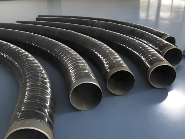
| Size: | OD: 1/2"-24" seamless, 26"-60" welded |
| WT: SCH5S,10S,10,40S,STD,XS,80S,XXS,40,60,80,160,XXS | |
| 30° 45° 60° 90° 180°,etc | |
| LR/long radius=1.5D,SR/Shrot radius=1D, various radius: 3D,4D,5D,6D,7D | |
| Pipe Standard: | ANSI B16.9, EN10253-4, DIN 2605, GOST 17375, JIS B2313, MSS SP 75 |
| Stainless Steel A403 WP 304/L,316/L,321,310S,347H,317,316Ti,904L | |
| ASTM A234 WP1/5/9/11/12/22/91 | |
| Duplex stainless steel: UNS31803, SAF2205, UNS32205, UNS31500 | |
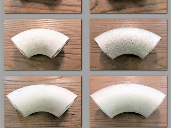
| Furface: | Pickled,sand blasting, rolling blast,brighten,polished,galvinizing,vanished |
| End: | Bevel end/PE/buttweld |
Pipe Fitting Elbow Introduction
Size:
OD: 1/2"-24" seamless, 26"-60" welded
WT: SCH5S,10S,10,40S,STD,XS,80S,XXS,40,60,80,160,XXS
30° 45° 60° 90° 180°,etc
LR/long radius=1.5D,SR/Shrot radius=1D, various radius: 3D,4D,5D,6D,7D
Pipe Standard:
ANSI B16.9, EN10253-4, DIN 2605, GOST 17375, JIS B2313, MSS SP 75
Stainless Steel A403 WP 304/L,316/L,321,310S,347H,317,316Ti,904L
ASTM A234 WP1/5/9/11/12/22/91
Duplex stainless steel: UNS31803, SAF2205, UNS32205, UNS31500
Furface:
Pickled,sand blasting, rolling blast,brighten,polished,galvinizing,vanished
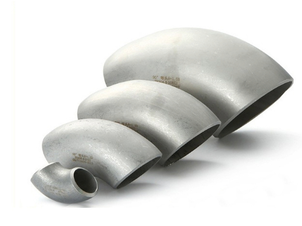
Steel Pipe Elbow is a key parts in a piping system for to change the fluid flow direction. It is used to connect two pipes with same or different nominal diameters, and to make the pipe turn to a certain direction of 45 degree or 90 degree or 180 degree.
Applications of Pipe Elbow Fittings:
Pipe elbows are manufactured to be used in flow lines for gases, fluids in industrial processes, medical, construction and many other specialized applications.
The elbows are constructed of heavy materials for rigid applications like extreme high/low temperature resistance etc.
The elbows are specifically designed for use on process and control systems, instrumentation, and equipment used in chemical, petroleum, fluid power, electronic and pulp and paper plants.
Types of Steel Pipe Elbows
The ends may be machined for butt welding (SW) or socketed welding(SW) etc.
Short Radius (SR) Elbow is also called SR elbow, – means the radius is 1.0 times the pipe diameter
Short radiu 45°Elbow: Short radius 45° elbow changes the direction by 45 degrees.
Short radius 90°Elbow: Short Radius 90° elbow is same as LR90 except for the measurement between end of elbow to center line is 1 x NPS.
Short radius 180° Elbow: Short Radius 180° return bend allows complete reversal of flow
Sizes:
Seamless elbow: 1/2"-24" DN15-DN600
Welding elbow: 6"-72" DN150-DN1800
Wall thickness: Sch5-Sch160 XXS
Long radius elbow is the elbow which the radius of curvature of is 1.5 times the diameter of the pipe; if the radius of curvature is greater than 1.5 times, the long radius elbow will be called the bend. The short radius elbow means that the radius of curvature of the elbow equals the diameter of the pipe, or 1 time the diameter of the pipe in common words. D is used to represent the diameter of the elbow.
Long Radius (LR) Elbow is also called LR elbow – means the radius is 1.5 times the pipe diameter
L/R 45°Elbow: Long radius 45 degree elbow changes the direction by 45 degrees.
L/R 90°Elbow: Long radius 90 degree elbow changes the direction by 90 degrees.
L/R 180°Elbow: Long Radius 180 degree return bend allows complete reversal of flow.
Sizes:
Seamless elbow: 1/2"-24" DN15-DN600
Welding elbow: 6"-72" DN150-DN1800
Wall thickness: Sch5-Sch160 XXS
|
Nominal pipe size |
Outside Diameter |
Center to End |
Center to Center |
Back to Faces |
||||||
|
45°Elbows |
90°Elbows |
180°Return |
||||||||
|
H |
F |
P |
K |
|||||||
|
DN |
INCH |
Series A |
Series B |
LR |
LR |
SR |
LR |
SR |
LR |
SR |
|
15 |
1/2 |
21.3 |
18 |
16 |
38 |
- |
76 |
- |
48 |
- |
|
20 |
3/4 |
26.9 |
25 |
16 |
38 |
- |
76 |
- |
51 |
- |
|
25 |
1 |
33.7 |
32 |
16 |
38 |
25 |
76 |
51 |
56 |
41 |
|
32 |
11/4 |
42.4 |
38 |
20 |
48 |
32 |
95 |
64 |
70 |
52 |
|
40 |
11/2 |
48.3 |
45 |
24 |
57 |
38 |
114 |
76 |
83 |
62 |
|
50 |
2 |
60.3 |
57 |
32 |
76 |
51 |
152 |
102 |
106 |
81 |
|
65 |
21/2 |
76.1(73) |
76 |
40 |
95 |
64 |
191 |
127 |
132 |
100 |
|
80 |
3 |
88.9 |
89 |
47 |
114 |
76 |
229 |
152 |
159 |
121 |
|
90 |
31/2 |
101.6 |
- |
55 |
133 |
89 |
267 |
178 |
184 |
140 |
|
100 |
4 |
114.3 |
108 |
63 |
152 |
102 |
305 |
203 |
210 |
159 |
|
125 |
5 |
139.7 |
133 |
79 |
190 |
127 |
381 |
254 |
262 |
197 |
|
150 |
6 |
168.3 |
159 |
95 |
229 |
152 |
457 |
305 |
313 |
237 |
|
200 |
8 |
219.1 |
219 |
126 |
305 |
203 |
610 |
406 |
414 |
313 |
|
250 |
10 |
273.0 |
273 |
158 |
381 |
254 |
762 |
508 |
518 |
391 |
|
300 |
12 |
323.9 |
325 |
189 |
457 |
305 |
914 |
610 |
619 |
467 |
|
350 |
14 |
355.6 |
377 |
221 |
533 |
356 |
1067 |
711 |
711 |
533 |
|
400 |
16 |
406.4 |
426 |
253 |
610 |
406 |
1219 |
813 |
813 |
610 |
|
450 |
18 |
457.2 |
478 |
284 |
686 |
457 |
1372 |
914 |
914 |
686 |
|
500 |
20 |
508.0 |
529 |
316 |
762 |
508 |
1524 |
1016 |
1016 |
762 |
|
550 |
22 |
559 |
- |
347 |
838 |
559 |
Note: |
|||
|
600 |
24 |
610 |
630 |
379 |
914 |
610 |
||||
|
650 |
26 |
660 |
- |
410 |
991 |
660 |
||||
|
700 |
28 |
711 |
720 |
442 |
1067 |
711 |
||||
|
750 |
30 |
762 |
- |
473 |
1143 |
762 |
||||
|
800 |
32 |
813 |
820 |
505 |
1219 |
813 |
||||
|
850 |
34 |
864 |
- |
537 |
1295 |
864 |
||||
|
900 |
36 |
914 |
920 |
568 |
1372 |
914 |
||||
|
950 |
38 |
965 |
- |
600 |
1448 |
965 |
||||
|
1000 |
40 |
1016 |
1020 |
631 |
1524 |
1016 |
||||
|
1050 |
42 |
1067 |
- |
663 |
1600 |
1067 |
||||
|
1100 |
44 |
1118 |
1120 |
694 |
1676 |
1118 |
||||
|
1150 |
46 |
1168 |
- |
726 |
1753 |
1168 |
||||
|
1200 |
48 |
1220 |
1220 |
758 |
1829 |
1219 |
||||
Visual inspection:
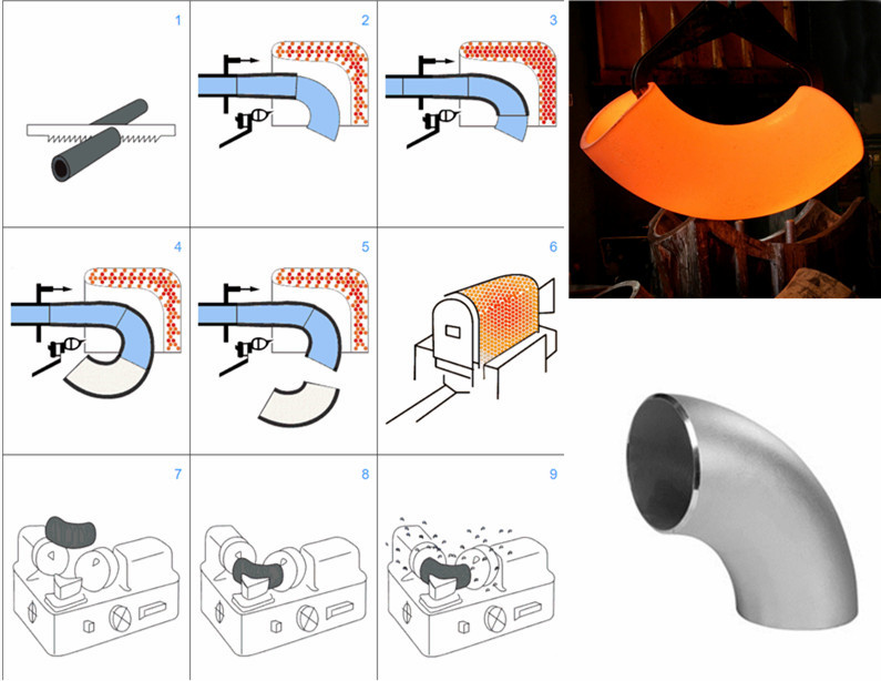
Generally based on the naked eye observation, sometimes with a 5-20 times magnifying glass for observation. Through visual inspection, surface defects of weld elbow welds, such as undercuts, welds, surface cracks, pores, slag inclusions, and weld penetration, can be found. The dimensions of the weld can also be measured using a weld detector or template.
Non-destructive testing:
Inspection of defects such as slag inclusions, pores and cracks hidden inside the weld. At present, the most common use is X-ray inspection, as well as ultrasonic flaw detection and magnetic flaw detection. Ultrasonic flaw detection is much simpler than X-ray photography and is therefore widely used. However, ultrasonic flaw detection often can only be judged based on operational experience, and can not leave a test basis. For internal defects that are not deep from the surface of the weld and extremely small cracks on the surface, magnetic flaw detection can also be used.
Hydraulic test and air pressure test:
For pressurized containers requiring sealing, hydraulic pressure test and/or air pressure test shall be carried out to check the sealing and pressure bearing capacity of the weld. The method is to inject 1.25-1.5 times working water or a working pressure gas (mostly air) into the container for a certain period of time, then observe the pressure drop in the container and observe whether there is leakage outside. According to these, it can be assessed whether the weld is qualified.
The mechanical performance test of the elbow:
Mon-destructive testing can find the inherent defects of the weld, but can not explain the mechanical properties of the metal in the heat affected zone of the weld, so sometimes the welded joint should be subjected to tensile, impact, bending and other tests. These tests were performed by the test panels. The test panels used are preferably welded together with the longitudinal joints of the cylinder to ensure consistent construction conditions. The test panels were then tested for mechanical properties. In actual production, only welded joints of new steel grades are generally tested in this respect.
|
NOMINAL PIPE SIZE NPS |
ANGULARITY TOLERANCES |
ANGULARITY TOLERANCES |
ALL DIMENSIONS ARE GIVEN IN INCHES. TOLERANCES ARE EQUAL PLUS AND MINUS EXCEPT AS NOTED. |
|
|
Off Angle Q |
Off Plane P |
(1) Out-of-round is the sum of absolute values of plus and minus tolerance. |
|
½ to 4 |
0.03 |
0.06 |
|
|
5 to 8 |
0.06 |
0.12 |
|
|
10 to 12 |
0.09 |
0.19 |
|
|
14 to 16 |
0.09 |
0.25 |
|
|
18 to 24 |
0.12 |
0.38 |
|
|
26 to 30 |
0.19 |
0.38 |
|
|
32 to 42 |
0.19 |
0.50 |
|
|
44 to 48 |
0.18 |
0.75 |
General Tolerances forpipe elbow of ASME B16.9
|
NPS |
DN |
O.D |
I.D |
Off Angle, Q |
Off Plane, P |
|
1/2~2-1/2 |
15~65 |
+1.6, -0.8 |
±0.8 |
±1 |
±2 |
|
3~3-1/2 |
80~90 |
±1.6 |
±1.6 |
±2 |
±4 |
|
4 |
100 |
±1.6 |
±1.6 |
±3 |
±5 |
|
5~8 |
125~200 |
+2.4, -1.6 |
±1.6 |
±3 |
±6 |
|
10~18 |
250~450 |
+4.0, -3.2 |
±3.2 |
±4 |
±10 |
|
20~24 |
500~600 |
+6.4, -4.8 |
±4.8 |
±5 |
±10 |
|
26~30 |
650~750 |
+6.4, -4.8 |
±4.8 |
±5 |
±13 |
|
32~48 |
800~1200 |
+6.4, -4.8 |
±4.8 |
±5 |
±19 |
* All dimensions are in mm unit. NPS: Nominal Pipe Size; DN: Nominal Diameter.
* O.D: outside diameter at bevel; I.D: inside diameter at end; Both P & Q are angularity tolerances.
* A minimum wall thickness of 87.5% should apply unless otherwise specified by the purchaser.
Tolerances of Center-to-End & Overall Length Dimensions
|
NPS |
DN |
*I |
*II |
*III |
*IV |
|
1/2~2-1/2 |
15~65 |
±2 |
±3 |
±2 |
±3 |
|
3~3-1/2 |
80~90 |
±2 |
±3 |
±2 |
±3 |
|
4 |
100 |
±2 |
±3 |
±2 |
±3 |
|
5~8 |
125~200 |
±2 |
±3 |
±2 |
±6 |
|
10~18 |
250~450 |
±2 |
±3 |
±2 |
±6 |
|
20~24 |
500~600 |
±2 |
±3 |
±2 |
±6 |
|
26~30 |
650~750 |
±3 |
±6 |
±5 |
±10 |
|
32~48 |
800~1200 |
±5 |
±6 |
±5 |
±10 |
* All dimensions are in mm unit.
* I refers to the tolerances for center-to-end dimensions of 90° & 45° long and short radius elbows and tees, A, B, C, M.
* II refers to the tolerances for center-to-end dimensions of 3D radius elbows, A, B.
* III refers to the tolerances for overall length of reducers and lap joint stub ends, F, H.
* IV refers to the tolerances for overall length of caps, E.
Chemical Composition (%) of ASTM A420
This specification covers wrought carbon steel and alloy steel fittings of seamless & welded construction intended for use at low temperatures. It covers four grades WPL6, WPL9, WPL3 & WPL8 depending upon chemical composition. Fittings WPL6 are impact tested at temp – 50° C, WPL9 at -75° C, WPL3 at -100° C and WPL8 at -195° C temperature.
The allowable pressure ratings for fittings may be calculated as for straight seamless pipe in accordance with the rules established in the applicable section of ASME B31.3.
The pipe wall thickness and material type shall be that with which the fittings have been ordered to be used, their identity on the fittings is in lieu of pressure rating markings.
|
Steel No. |
Type |
Chemical composition |
||||||||||||
|
C |
Si |
S |
P |
Mn |
Cr |
Ni |
Mo |
Other |
σb |
σs |
d5 |
HB |
||
|
WPL6 |
0.3 |
0.15-0.3 |
0.04 |
0.035 |
0.6-1.35 |
0.3 |
0.4 |
0.12 |
Cb:0.02;V:0.08 |
415-585 |
240 |
22 |
|
|
|
WPL9 |
0.2 |
|
0.03 |
0.03 |
0.4-1.06 |
|
1.6-2.24 |
|
|
435-610 |
315 |
20 |
|
|
|
WPL3 |
0.2 |
0.13-0.37 |
0.05 |
0.05 |
0.31-0.64 |
|
3.2-3.8 |
|
|
450-620 |
240 |
22 |
|
|
|
WPL8 |
0.13 |
0.13-0.37 |
0.03 |
0.03 |
0.9 |
|
8.4-9.6 |
|
|
690-865 |
515 |
16 |
|
|
Long Radius (LR) Elbows per ASME B16.9: Centerline radius equals 1.5 × NPS. Provides 60-70% lower pressure drop than SR alternatives. Minimizes turbulence-induced erosion at downstream pipe wall, critical for slurry, gas携带固体颗粒, and high-velocity applications. Preferred configuration for all standard manufactured butt weld elbows.
Short Radius (SR) Elbows: Centerline radius equals 1.0 × NPS. Compact design reduces material cost by 25-35% and installation space requirements. Applicable for low-pressure utility systems, building services, and low-velocity water distribution. Note: SR elbows generate 2-3x higher pressure loss and increased flow-induced vibration.
Selection Criteria: Specify LR for NPS > 4 in hydrocarbon service, slurry lines, or anywhere pump/compressor suction piping is involved. Reserve SR for confined mechanical rooms, low-pressure HVAC, and budget-sensitive projects where lifecycle cost analysis permits.
ASME B16.9 Compliance: Dimensional standard covering NPS 1/2 through NPS 48. Tolerance requirements for OD, wall thickness, and center-to-end dimensions strictly enforced. All manufactured elbows are LR (1.5D) by default unless SR is specifically ordered.
ASME B16.28: Covers wrought LR and SR 45° and 90° elbows for NPS 1/2 through NPS 4. Alternative specification for small-bore fabricated elbows with potentially different wall thickness requirements.
Bevel Preparation per ASME B16.25: Standard bevel angle 30°±5° with 1/16 inch land. Critical for achieving full penetration welds without burn-through or incomplete fusion. Field weld preparation must match factory bevel dimensions.
Material Traceability: Heat number identification mandatory per ASME A960. Material test reports per ASTM/ASME specifications must accompany each shipment. PMI verification recommended for critical service applications.
Carbon Steel ASTM A234: WPB grade for general service ( -20°F to 800°F). WPC for elevated temperature applications to 850°F. WPL6/WPL9 for low-temperature service to -75°F per ASME B31.3 Chapter VIII. WPHY grades (42/46/52/60/65/70) with enhanced impact requirements for pipeline transmission systems.
Stainless Steel ASTM A403: WP304/304L for general corrosion-resistant applications. WP316/316L with 2-2.5% molybdenum for chloride-containing environments and coastal installations. WP321 stabilized grade prevents sensitization in welded assemblies. WP310S for thermal cycling and high-temperature applications to 2,100°F.
Alloy Steel ASTM A234: WP11 (1.25Cr-0.5Mo) for petroleum refining to 1,000°F. WP22 (2.25Cr-1Mo) for hydrocracker and delayed coker service. WP91/WP92 (9Cr-1Mo-V) for ultra-supercritical power generation at temperatures exceeding 1,100°F.
Crane Technical Paper 410 K-Values: LR 90° elbow K ≈ 0.3 × (D/L)^0.5, simplified to K ≈ 0.2 for standard 1.5D configuration. SR 90° elbow K ≈ 0.7 × (D/L)^0.5, simplified to K ≈ 0.7. 45° elbow K approximately 40% of corresponding 90° value.
Pressure Drop Formula: ΔP = K × ρV²/2g, where ρ is fluid density (lb/ft³), V is velocity (ft/s), g is gravitational constant (32.2 ft/s²). For water at 10 ft/s velocity through LR 90° elbow: ΔP ≈ 0.31 psi per elbow.
Multi-Phase Flow Consideration: Elbows in gas-liquid multi-phase flow cause phase separation and stratified flow development. Oversize elbows (1D or 2D) can mitigate phase maldistribution but increase cost. Consult Beggs & Brill correlation for detailed multi-phase pressure loss calculations.
Erosion Velocity Limit: API 14E recommends limiting velocity in elbowed piping to Vmax = C/√ρ where C = 100 (continuous service) or 125 (intermittent service). Erosion rate proportional to V^2.7 in sand-laden service; consider weld overlay or hardfacing at elbow extrados.
Dimensional Verification: OD tolerance ±0.031 inch for NPS <12, ±0.0625 inch for NPS ≥12. Wall thickness at any point shall not be less than specified minimum. Center-to-end dimension tolerance ±0.0625 inch per ASME B16.9 Table 1.
Non-Destructive Examination: Visual inspection mandatory per ASME A960 for surface defects, weld quality, and marking legibility. Liquid penetrant or magnetic particle examination available for ferritic materials. Radiographic or ultrasonic examination for critical service butt weld ends.
Hydrostatic Testing: Standard test pressure equals 1.5× design pressure (typically limited to 2,500 psi standard). Extended hold time of 5 minutes minimum to detect seepage. Document test pressure, hold duration, and pass/fail criteria.
Hardness Testing: Mandatory for alloy steel grades per ASME A960. Maximum Brinell hardness 197 HBW for WPB/WPC materials. Verify PWHT completion where post-weld heat treatment is code-specified for P1, P3, P4, P5A materials.
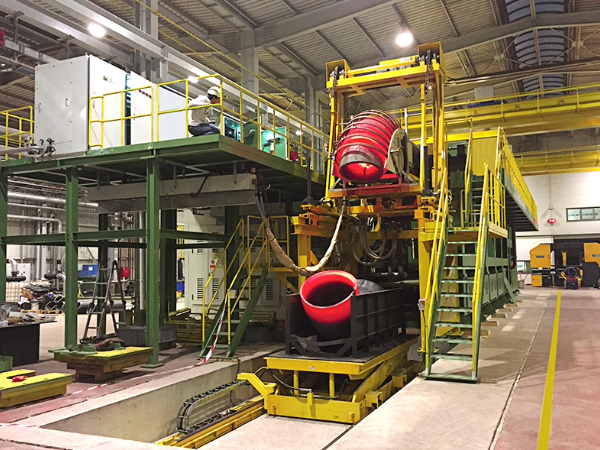
Fabricated LR/SR Elbows: Produced by piecing and welding pipe segments. Wall thickness typically matches pipe schedule. LR fabricated = 1.5D radius, SR = 1.0D radius. Economical for large diameters (NPS > 24) where forming tooling is unavailable. Weld seam location must be documented; avoid placing longitudinal welds at 0° or 90° positions.
3D/5D/7D Large-Radius Bends: Pipe bending process produces smooth flow path with minimal pressure drop. Standard for offshore platforms, FPSO vessels, and long-distance pipelines. 3D bend offers 50% pressure drop reduction versus LR elbow. 5D/7D bends for ultra-low velocity applications and erosion-prone slurry transport.
Mitered Elbows: Multiple pipe segments welded at angles to approximate curved radius. 5-piece miter ≈ standard LR performance. 3-piece miter acceptable for low-pressure, low-velocity service. Each miter joint requires full penetration weld and NDE examination. Less economical than formed elbows for NPS > 12.
Induction Bending: Heat induction process produces consistent wall thickness and smooth bore. Radius capability from 1.5D to 5D+ with tight ovality control (±5%). Preferred method for offshore pipelay applications requiring long-radius multi-plane bends. Higher cost justified by superior flow characteristics and reduced installation fit-up complexity.