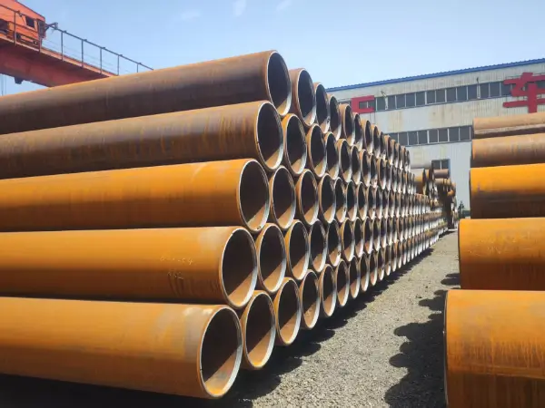
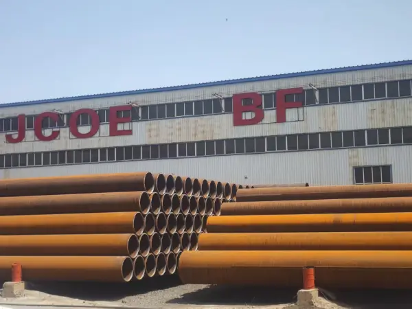
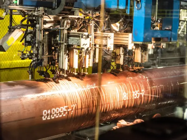
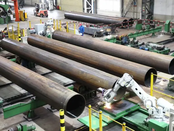
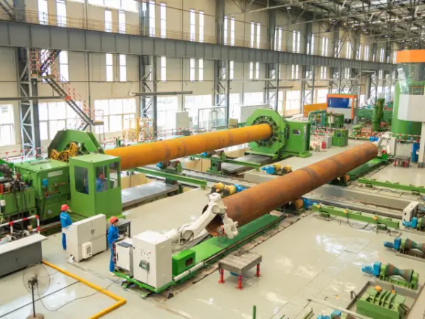
LSAW Steel Pipe Specification
|
Product
|
LSAW Pipe, Longitudinally Submerged Arc Welding Pipe
|
|
Application
|
Used for Oil / Gas / Water Transmission, Engineering / Offshore Projects
|
|
Size
|
OD: 219mm-1626mm
|
|
|
WT:6.35 mm – 60 mm
|
|
|
LENGTH: 5.8/6/11.8/12m
|
|
Pipe Standard
|
API 5L PSL1/PSL2 Gr.A,Gr.B,X42,X46,X52,X56,X60,X65,X70
|
|
|
ASTM A53/A252/A500/A672/A691/A139
|
|
|
EN10210/EN10219/EN10217/EN10208/EN10297
|
|
|
AN/NZS 1163 AN/NZS 1074
|
Product Display & Application
UOE SAWL Pipes
|
Outside Diameter
|
Φ219mm- 1118mm (20"- 44")
|
|
Wall Thickness
|
6.0-25.4mm 1/4"-1"
|
|
Quality Standards
|
API、DNV、ISO、DEP、EN、ASTM、DIN、BS、JIS、GB、CSA
|
|
Length
|
9-12.3m (30'- 40')
|
|
Grades
|
API 5L A-X90,GB/T9711 L190-L625
|
JCOE SAWL Pipes
|
Outside Diameter
|
Φ406mm- 1626mm (16" - 64" )
|
|
Wall Thickness
|
6.0- 75mm (1/4" - 3" )
|
|
Quality Standards
|
API、DNV、ISO、DEP、EN、ASTM、DIN、BS、JIS、GB、CSA
|
|
Length
|
3-12.5m ( 10'- 41' )
|
|
Grades
|
API 5L A-X100, GB/T9711 L190-L690
|
Features Of Longitudinally Submerged Arc Welding Steel Pipe
- Large diameter
- Thick walls
- High pressure resistance
- Low temperature resistance
UOE LSAW Pipe Forming Process:
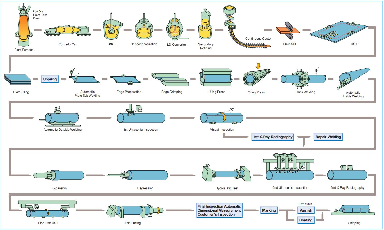
The three main forming processes of UOE LSAW steel pipe forming process include: steel plate pre-bending, U forming and O forming. Each process adopts a dedicated forming press to complete the three processes of pre-bending the edge of the steel plate, U forming and O forming in sequence to deform the steel plate into a circular tube.
 JCOE LSAW Pipe Forming Process:
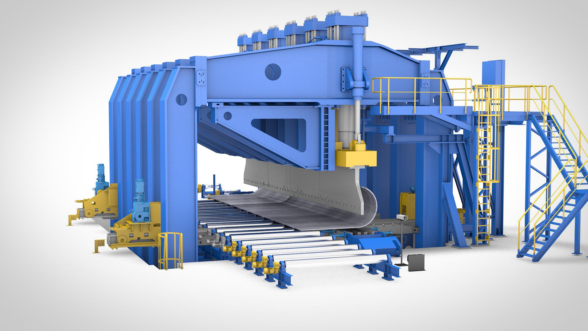
After several steps of stamping on the JCO forming machine, first half of the steel plate is pressed into a "J" shape, then the other half of the steel plate is pressed into a "J" to form a "C" shape, and finally pressurized from the middle to form An open "O"-shaped tube blank is formed.
- Chemical Component Analysis
- Mechanical Properties
- Elongation, Yield Strength, Ultimate Tensile Strength
- Technical Properties
- DWT Test, Impact Test, Blow Test, Flattening Test
- X-Ray Test
- Exterior Size Inspection
- Hydrostatic Test
- UT Test
Frequently Asked Questions
1. What is the mechanical difference between JCOE and UOE forming?
The difference is in HOW the steel yields:
JCOE — incremental bending:
The plate passes through 5-7 presses, each incrementally increasing curvature. The material experiences repeated plastic deformation with spring-back after each press. This creates non-uniform residual stress around the circumference — areas near pressing points yield more.
UOE — continuous bending:
The plate forms through three dedicated dies (U-die, O-die, expand die) in one continuous pass. The expand die applies excessive calibration force to over-form and spring back to target size.
Key consequences:
JCOE ovality: 1.5-2.5% (spring-back variation between presses)
UOE ovality: 0.5-1.0% (calibrated die geometry)
For high-pressure pipelines per API 5L Section 8.3, UOE's consistent geometry reduces stress concentration at field welds.
2. Why is JCOE more economical for thick-wall (≥25mm) LSAW?
Two reasons: equipment and material handling.
Equipment:
JCOE uses hydraulic stamping presses (5000-10000 ton) — widely available, lower capital investment. UOE requires dedicated U/O/expand die sets precision-machined for each OD range, with higher tooling costs.
Material input:
UOE feeding requires flat plate of exact dimensions per ASTM A6. JCOE can use coil with on-site edge preparation. For thick plates (≥25mm), this flexibility reduces material procurement complexity.
Production setup:
JCOE die changes take 2-4 hours; UOE die changes take 8-16 hours. For custom specifications or short production runs, JCOE offers faster turnaround.
3. How does LSAW handle the double-side weld challenge for thick-wall pipes per API 5L Section 10?
Thick-wall LSAW (≥25mm) requires both inside and outside submerged arc welding per API 5L Section 10.2:
Inside welding challenges:
(1) Access restriction — welding carriage must fit inside pipe
(2) Heat accumulation — multiple passes needed to fill groove
(3) Slag removal — between passes to prevent inclusions per AWS D1.1
Standard solutions:
(1) Dual-wire SAW — two electrodes simultaneously for higher deposition rate per ASME Section IX QW-409
(2) Process control — heat input calculated per kJ/mm to prevent distortion
(3) Inter-pass temperature — controlled below 200°C to prevent HAZ cracking per API 1104 Table 5
(4) UT examination — both inside/outside weld 100% ultrasonically tested per ASTM A1060
Welds meet API 1104 requirements for full penetration and weld strength.
4. What makes LSAW suitable for offshore deep-water pipeline per DNV-OS-F101?
Offshore applications per DNV-OS-F101 require LSAW capabilities:
(1) Wall thickness — up to 70mm for deep-water pressure (30-1500m water depth)
(2) Weld quality — double-side SAW with 100% UT meets DNV-OS-F101 Sec 6
(3) Toughness — Charpy V-notch ≥ 40J at -20°C per DNV-OS-F101 Table 5-2
(4) Dimensional control — out-of-roundness ≤1.5% for reeling onto lay vessels
(5) Manufacturing tolerance — OD tolerance ±1.0mm per API 5L Table 9
(6) Sour service — PSL2 with restricted S≤0.001% per NACE MR0175
5. How does LSAW achieve dimensional accuracy compared to SSAW per API 5L Table 9?
LSAW dimensional advantages per API 5L Table 9 and EN10219:
(1) Forming method — dies precisely control pipe geometry vs continuous coil feed
(2) End tolerance — ±1.5mm OD vs ±3-5mm for SSAW
(3) Wall thickness — ±5% vs ±10% for SSAW
(4) Straightness — ≤3mm/m vs ≤5mm/m for SSAW
Measurement methods:
(1) Laser OD scanners at each production station per ISO 11960
(2) UT wall thickness at 0°, 90°, 180°, 270° around circumference per ASTM A1060
(3) Straightness laser alignment with auto-correction
6. What are the critical parameters for LSAW sour service (H₂S) per NACE MR0175/ISO 15156?
Sour service per NACE MR0175/ISO 15156 Section 7:
Material requirements:
(1) Maximum hardness — ≤ 22 HRC in weld and HAZ per ISO 15156 Table A.1
(2) Carbon equivalent — CE≤0.40% per API 5L Section 9.2
(3) Chemical limits — C≤0.10%, Mn≤1.60%, S≤0.001% per NACE MR0175 Table 2
Manufacturing controls:
(1) PWHT at 580-620°C for 1hr per ASME Section VIII UCS-56
(2) Impact testing — CVN at -20°C per API 5L Table 11
(3) Hardness survey across weld, HAZ, and base metal per ISO 6507-1
Testing requirements:
(1) 100% UT of welds per ASTM A1060
(2) Hydrostatic test at 80% SMYS per API 5L Section 9.4