

Steel plate Introduction
|
Product: |
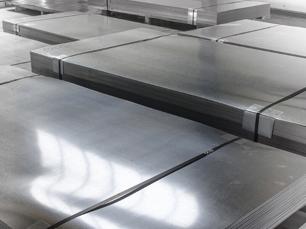
Stainless Steel Sheet, 304 Stainless Steel Plate, 316 Stainless Steel Plate |
|
Application: |
In Chemical Industry, Coal, Oil Field Open Machine, Building Materials Heat-resistant Parts |
|
3/16'' Thick ~ 6'' Thick, Up to 120'' Wide |
|
|
Pipe Standard: |
ASTM A167, ASTM A176, ASTM A240, ASTM A693, ASTM A480 |
|
Steel Grades: |
300 Series Stainless, 400 Series Stainless |
|
Surface: |
Sweet Service, Sour Service, Anti-H2S, NACE MR0175/ISO15156 |
|
Zinc Coating: |
10~50 g/m2 |
|
Packing: |
Waterproof Paper Wrapped, Packed in Wooden Cabins |
Tensile strength, elongation, hardness, and bending tests of skin-passed materials (S)
|
Remarks |
Steel type |
Tensile strength, N/mm2 |
Elongation, % |
Hardness |
Bending test |
|||||||
|
Classification by nominal thickness, mm |
Takasago special standard |
|||||||||||
|
0.25= |
0.25= |
0.30= |
0.40= |
0.60= |
1.0= |
1.6= |
2.5= |
HV |
HRBS |
|||
|
General |
SPCC-SB |
- |
- |
- |
- |
- |
- |
- |
- |
=115 |
=65 |
Bend angle: 180° |
|
SPCCT-SB |
270= |
26= |
29= |
32= |
34= |
35= |
36= |
37= |
=115 |
=65 |
||
|
Drawing |
SPCD-SB |
270= |
28= |
31= |
34= |
36= |
37= |
38= |
39= |
=115 |
=65 |
|
|
Deep drawing |
SPCE-SB |
270= |
30= |
33= |
36= |
38= |
39= |
40= |
41= |
=115 |
=65 |
|
* No. 5 test pieces are to be used for tensile testing.
Hardness and bending tests of hardened materials
|
Skin-pass |
Skin-pass symbol |
Rockwell hardness |
Vickers hardness |
Bending test |
||
|
HRBS |
HV |
Bending angle |
Inner radius |
Bending test piece |
||
|
1/8 hardness |
8 |
50 - 71 |
95 - 130 |
180° |
Adhesion |
JIS No. 3 test piece |
|
1/4 hardness |
4 |
65 - 80 |
115 - 150 |
180° |
Half of thickness |
|
|
1/2 hardness |
2 |
74 - 89 |
135 - 185 |
180° |
Equal to thickness |
|
|
Full hard |
1 |
85= |
170= |
- |
- |
|
* Normally, the bending test is omitted.
Tensile Test
By definition, tensile is defined as the capability of a material to become stretched or drawn out until cracks or stresses begin to show. Another more common term is "tensile strength" which is the resistance of breaking under impacts or stresses. This term is used to describe the limit at which steel or any ductile material transforms from temporary elasticity to permanent deformation. To put it simply, when a material has been stretched past its tensile strength rating, it will break apart.
In sheet metal fabrication, undertaking tensile tests or tensile strength tests is important because it predicts the reproducibility of a given product. This is especially useful for the mass production of metal goods, wherein each product must have relatively the same measurements for tensile strength. For example, even if a single sheet of a metal coil is formed in the same facility, material characteristics will still vary, affecting the quality of the part and scrap rate.
As one of the most common methods for testing metal, tensile strength tests are widely available and can be done on universal testing machines (UTMs) that are also capable of other types of mechanical tests. In this case, a small sample of sheet metal is loaded into the machine and drawn out. The operator records the specimen's maximum load values, as shown on a computer screen.
Fatigue Test
Another type of metal testing method is known as the fatigue test. Unlike tensile strength tests where a specimen is subject to only a single complete execution, fatigue testing is done under a cyclical load that constantly adds stress to the material. This is done at a certain frequency or alternating load tests in order to measure tension or compression.
Material failure in fatigue testing takes place when damage begins showing on the specimen after being subjected to frequent repetitions of stress. This type of testing is crucial in understanding why metal components that have been used for long periods may suddenly fail. Oftentimes this failure occurs not because of a single overload, but a continuous pattern of cyclical stress drawn out for a certain timeframe.
Fatigue testing methods can be further subcategorized into a high cycle or low cycle testing. For the high cycle test, the finite life fatigue strength and the high cycle fatigue strength are determined. Some examples of these two types in action can be found in turbine blades or stationary power-generating turbines that undergo disc strain when in constant use.
Hardness Testing
Most mild steel or low carbon steel sheet metals that are 1.5 millimeters in thickness will most likely have a Rockwell B hardness rating. Rockwell hardness is simply the measuring range that determines the resistance of a material to permanent deformity and penetration by another material. This is usually done for certain types of steel, such as tool and cutting steel which is engineered to be more durable than the typical.
As mentioned before, mild steel will record a Rockwell B hardness rating that falls in the mid to high 70s. Three main components are involved in this type of testing – the indenter, anvil, and the specimen. Here's a brief illustration of the process:
The minor load is pressed onto the specimen and generates a reference depth for the measurement. For Rockwell B, around 10 kg/cm2 of force is used.
To achieve a deeper penetration, an additional load is pressed onto the surface of the sheet metal. It is removed then a minor load is re-applied.
The Rockwell B hardness rating is calculated by measuring the difference between the depth and the reference depth done on the material.
Hole Expansion Test
Hole expansion testing is specific for punched sheet metals and is done to assess the ductility (the ability of the material to be formed into a wire without breaking) on the sheet metal's edges. This method is applicable especially for high-strength steel products, which face challenges on edge cracks, especially when sheared.
The hole expansion test starts off with shearing a 10mm-diameter hole and widened using a conical punch at 60°. The resulting ratio of the expanded diameter to the initial measurement is subsequently known as the hole expansion ratio. Since shearing creates significant alterations to the material's forming properties for sheet metal edges, this technique proves to be a fast and economic way of measuring the change.
Steel Sheet Thickness tolerances
|
Unit: mm |
||||||||
|
Classification by nominal thickness |
JIS G 3141 thickness tolerance B |
Takasago special standard |
||||||
|
|
160= |
250= |
400= |
S standard |
SS standard |
U standard |
||
|
0.25= |
<0.40 |
±0.025 |
±0.030 |
±0.035 |
±0.035 |
±0.015 |
±0.012 |
±0.010 |
|
0.40= |
<0.60 |
±0.035 |
±0.040 |
±0.040 |
±0.040 |
±0.020 |
±0.016 |
|
|
0.60= |
<0.80 |
±0.040 |
±0.045 |
±0.045 |
±0.045 |
±0.023 |
±0.018 |
±0.012 |
|
0.80= |
<1.00 |
±0.04 |
±0.05 |
±0.05 |
±0.05 |
±0.026 |
±0.020 |
±0.014 |
|
1.00= |
<1.25 |
±0.05 |
±0.05 |
±0.05 |
±0.06 |
±0.030 |
±0.022 |
±0.016 |
|
1.25= |
<1.60 |
±0.05 |
±0.06 |
±0.06 |
±0.06 |
±0.035 |
±0.025 |
±0.018 |
|
1.60= |
<2.00 |
±0.06 |
±0.07 |
±0.08 |
±0.08 |
±0.040 |
±0.030 |
±0.020 |
|
2.00= |
<2.50 |
±0.07 |
±0.08 |
±0.08 |
±0.09 |
±0.050 |
±0.035 |
±0.030 |
|
2.50= |
<3.15 |
±0.08 |
±0.09 |
±0.09 |
±0.10 |
±0.060 |
±0.040 |
- |
|
3.15= |
<4.00 |
±0.09 |
±0.10 |
±0.10 |
±0.11 |
±0.070 |
±0.050 |
- |
|
4.00= |
<5.00 |
±0.10 |
±0.10 |
±0.11 |
±0.11 |
±0.08 |
±0.06 |
- |
|
5.00= |
<6.00 |
±0.12 |
±0.12 |
±0.13 |
±0.13 |
±0.09 |
±0.07 |
- |
|
6.00= |
=7.00 |
±0.15 |
±0.15 |
±0.17 |
±0.17 |
±0.10 |
±0.08 |
- |
Notes
1. The thickness of a steel strip is typically measured at a point within 15 mm of the edges. For pieces less than 30 mm in width, thickness is measured at the center.
2. To order sizes not listed above, please feel free to contact us.
3. Costs are higher for products made to meet special standards (SS and U).
Steel Sheet Width tolerances
|
Unit: mm |
|||||
|
Classification by nominal thickness |
JIS G 3141 width tolerances C |
||||
|
<160 |
160= |
250= |
400= |
||
|
|
<0.60 |
±0.15 |
±0.20 |
±0.25 |
±0.30 |
|
0.60= |
<1.00 |
±0.20 |
±0.25 |
±0.25 |
±0.30 |
|
1.00= |
<1.60 |
±0.20 |
±0.30 |
±0.30 |
±0.40 |
|
1.60= |
<2.50 |
±0.25 |
±0.35 |
±0.40 |
±0.50 |
|
2.50= |
<4.00 |
±0.30 |
±0.40 |
±0.45 |
±0.50 |
|
4.00= |
<5.00 |
±0.40 |
±0.50 |
±0.55 |
±0.65 |
|
5.00= |
<6.00 |
±0.50 |
±0.60 |
±0.65 |
±0.80 |
|
6.00= |
=7.00 |
±0.60 |
±0.70 |
±0.75 |
±0.80 |
Steel Plate Squareness
A/B ratio must be 1.0% or less.
Steel Plate Length tolerances
|
Unit: mm |
|
|
Classification by nominal thickness |
JIS G 3141 length tolerances A |
|
800= - <2000 |
+10 |
|
2000= - <2800 |
+15 |
Max. camber A
|
Unit: mm |
|||
|
Classification by nominal thickness |
Steel sheet in lengths of |
Steel sheet or strip in lengths of |
Notes |
|
10= - <20 |
24 |
24 per any length of 2,000 |
Takasago special standard |
|
20= - <30 |
16 |
16 per any length of 2,000 |
|
|
30= - <40 |
8 |
8 per any length of 2,000 |
JIS G 3141 |
|
40= - <450 |
4 |
4 per any length of 2,000 |
|
* Excluding SUY and SUYP
JIS G 3141 Standard
|
Steel type symbol |
Skin-pass symbol |
Steel grade |
Chemical composition, % |
|||||
|
C |
Si |
Mn |
P |
S |
||||
|
General |
SPCC |
S |
TAP8 |
=0.10 |
=0.08 |
0.20 - 0.50 |
=0.035 |
=0.035 |
|
8 |
TAK8 |
=0.08 |
=0.08 |
0.20 - 0.40 |
=0.025 |
=0.030 |
||
|
4 |
TAK10 |
0.08 - 0.12 |
=0.10 |
0.30 - 0.60 |
=0.030 |
=0.035 |
||
|
2 |
TAK12 |
0.10 - 0.14 |
=0.10 |
0.30 - 0.60 |
=0.030 |
=0.035 |
||
|
1 |
TAK20(*1) |
0.18 - 0.23 |
=0.10 |
0.30 - 0.60 |
=0.025 |
=0.030 |
||
|
Drawing |
SPCD |
S |
TAP8 |
=0.10 |
=0.08 |
0.20 - 0.50 |
=0.035 |
=0.035 |
|
TAK8 |
=0.08 |
=0.08 |
0.20 - 0.40 |
=0.025 |
=0.030 |
|||
|
Deep |
SPCE |
S |
TAK8 |
=0.08 |
=0.08 |
0.20 - 0.40 |
=0.025 |
=0.030 |
(*1)TAK20 cannot be applied to the SPCC-SB type specified in JIS G 3141.
JIS G 3141 Standard
|
Steel type symbol |
Chemical composition, % |
|||
|
C |
Mn |
P |
S |
|
|
SPCC |
=0.15 |
=0.60 |
=0.100 |
=0.035 |
|
SPCD |
=0.10 |
=0.50 |
=0.040 |
=0.035 |
|
SPCE |
=0.08 |
=0.45 |
=0.030 |
=0.030 |
SAE Standard
|
Steel type symbol |
Chemical composition, % |
|||
|
C |
Mn |
P |
S |
|
|
SAE1008 |
=0.10 |
0.30 - 0.50 |
=0.030 |
=0.05 |
|
SAE1010 |
0.08 - 0.13 |
0.30 - 0.60 |
=0.030 |
=0.05 |
|
SAE1012 |
0.10 - 0.15 |
0.30 - 0.60 |
=0.030 |
=0.05 |
|
SAE1020 |
0.18 - 0.23 |
0.30 - 0.60 |
=0.030 |
=0.05 |
These are the two most commonly confused structural plate grades. The choice is not arbitrary—it has fabrication and cost implications.
ASTM A36 is the "general-purpose" structural plate. Yield: 250 MPa (36 ksi), tensile 400-550 MPa. The key advantage is weldability: A36 has carbon content typically ≤0.25-0.29% (depending on thickness), and most heats are produced to fine-grain practice even if not required. This means you can weld A36 with standard E7018 electrodes without preheat up to ~25mm thickness. A36 is the default choice when the engineer specifies "structural steel plate" without further qualification—it is acceptable for most building structures, platforms, and general fabrication.
ASTM A572 Grade 50 (345) is a high-strength low-alloy (HSLA) plate. Yield: 345 MPa (50 ksi), tensile 450-600 MPa. The yield strength advantage means you can use thinner plates to achieve the same section modulus—a 20% thickness reduction is often achievable. This saves weight (and cost) in large structures. However, A572 Gr50 has tighter chemistry controls (columbium-vanadium microalloying) and the thicker plates (≥25mm) may require preheat at 65-150°C before welding. If your structure is weight-sensitive (cranes, bridges, heavy equipment frames), specify A572 Gr50. If weldability and fabrication simplicity are priorities, A36 remains appropriate.
The real-world decision: Get a weight take-off for both options. If A572 Gr50 saves 500kg on a 5-tonne structure, the material cost differential (typically 10-15% premium for A572) may be offset by freight savings and the structural benefit of reduced self-weight. For plates over 50mm thickness, check whether A572 Gr50 is even available in your region—production is more limited.
Most buyers ignore through-thickness properties until they experience a welded joint failure. Here is why it matters:
What happens in thick welded plates: When you weld a thick plate (say, 40mm) in a multi-pass joint, the weld metal and heat-affected zone contract as they cool. This creates through-thickness tensile stresses perpendicular to the plate surface. If the plate has low through-thickness ductility (Z-direction), the stresses can exceed the steel's capacity, causing lamellar tearing—a crack that propagates parallel to the plate surface, often below the weld bevel.
Z-quality plates (specified as ASTM A770 or EN 10164) are tested with tensile specimens oriented perpendicular to the plate surface. The requirement is typically reduction of area ≥20-35% at the z-axis. Production of Z-quality plates requires low sulfur content (≤0.010%, preferably ≤0.005%) and often controlled rolling to produce a fine, pancake grain structure.
When is Z-quality mandatory?
(1) When stiffeners or brackets are welded to the face of a thick plate with fillet welds (common in ship hulls, pressure vessels, offshore structures);
(2) Thick flanges in offshore jacket structures where wave loads create z-direction stresses;
(3) Any joint where the designer has calculated through-thickness stresses and specified Z-quality;
(4) When using T-joint or corner joint configurations with full-penetration welds on plates >30mm.
When is it overkill? Butt-welded panels where loading is in-plane, thin plates (<20mm), or joints where weld geometry allows the stresses to be accommodated without forcing z-direction loading. Specify Z-quality only when engineering analysis demands it—unnecessary Z-quality adds cost and may not be stocked locally, extending your delivery time by 4-8 weeks.
ASTM A578/A578M specifies three levels of ultrasonic examination for plate. Understanding which level your application requires avoids both under-testing (risk oflamination failures) and over-specification (unnecessary cost and mill lead time).
Level A (least stringent): Straight-beam examination at the discretion of the manufacturer. Used as a process control check, not as an acceptance criterion. Level A is essentially a preliminary scan—the mill uses it to identify gross defects, but you cannot use the A578A certificate to accept or reject material. Do not accept Level A for critical applications.
Level B: Straight-beam examination at 100% coverage with referenced blocks (typically 1.6mm or 2.0mm flat-bottomed holes) as acceptance references. Discontinuities that produce indications exceeding the reference flaw amplitude are rejected. Level B is acceptable for general structural applications where laminations could cause fabrication problems but catastrophic failure is not anticipated.
Level C is the standard requirement for:
(1) Pressure vessel plates where lamination could cause catastrophic failure (ASME Sec. VIII);
(2) Offshore platform deck plates subject to dynamic loading;
(3) Cryogenic service plates where notch toughness is critical;
(4) Any application where the designer specifies "Level C per ASTM A578."
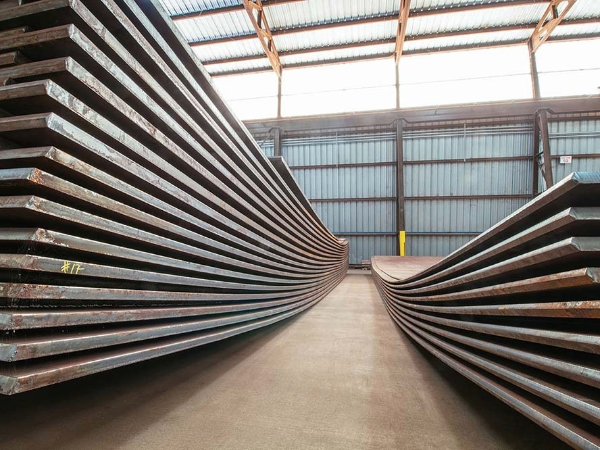
Camber is longitudinal curvature—a plate that curves along its length like a banana. Edge camber is curvature in the plane of the plate (the plate edge is not straight). Both are controlled by ASTM A6 tolerances, but even compliant camber can cause problems in automated cutting and welding operations.
Why plates develop camber: During hot rolling, differential cooling rates between the top and bottom surfaces cause the plate to warp. The cooler surface contracts more, creating curvature. Quenched plates can develop camber from non-uniform quench rates. Plate mills have straightening presses, but residual camber of 2-4mm per 6000mm is common.
Fabrication impact:
(1) In plasma or laser cutting, camber causes the plate to shift on the CNC table, creating dimensional errors in long parts;
(2) When edge milling for butt-welding, a cambered plate may not sit flat on the milling machine bed;
(3) For flanging or pressing operations, camber creates uneven pressure distribution;
(4) For ballistic or armor plate, camber affects ballistic performance.
What to specify: If camber is critical, specify special camber tolerances (typically ≤2mm per 6000mm for precision applications). If you are buying standard mill camber, plan for an edge milling or flattening operation before CNC cutting. Hot-rolled coil cut-to-length plate typically has better flatness than discrete plate from a reversing mill because the temper pass provides more uniform reduction. Discuss your flatness requirements with us before ordering—mill adjustments are cheaper than fabrication rework.
Positive Material Identification (PMI) is the practice of verifying that the material received matches the specification using portable analytical instruments. It is standard practice in critical industries—petrochemical, power generation, pressure equipment—but many buyers skip it until they receive a mis-shipment.
Handheld XRF (X-ray fluorescence) is the most common PMI tool. Modern instruments can identify alloy families in seconds: 304 vs. 316 vs. carbon steel is unambiguous. For precise chemistry verification, look for mode accuracy of ±0.03-0.05% for carbon and alloying elements. Budget instruments (under $10,000) are adequate for yes/no alloy identification but may not have sufficient precision for verifying carbon content or sulfur levels.
PMI protocol at receiving:
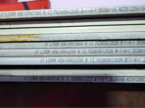
(1) Verify heat number on the plate matches the MTC;
(2) Take readings at a minimum of 3 locations (center and two edges)—beware of edge effects where carbon content may differ;
(3) For critical applications, verify the actual plate, not just the bundle tag;
(4) Document results with instrument serial number, operator, date, and location reading;
(5) If PMI shows deviation from MTC, quarantine the material and request a third-party laboratory analysis before fabrication.
Common mis-shipment scenarios caught by PMI: Wrong grade shipped (316L instead of 304), wrong heat (carbon content out of spec), wrong specification (A516 Gr60 instead of Gr70). In pressure vessel applications, using the wrong plate grade can void your ASME stamp and create legal liability—PMI is insurance against catastrophic consequences.
Material specification for welded structures involves more than just choosing a grade. Here are the specification details that determine fabrication success:
(1) Carbon equivalent (CE) and preheat requirements: For HSLA plates like A572 Gr50, A588, or A841, the mill's MTC should report CE value. The formula commonly used is CET = C + (Mn+Mo)/10 + (Cr+V)/20 + Ni/40 (or IIW CEV = C + Mn/6 + (Cr+Mo+V)/5 + (Ni+Cu)/15). Higher CE means stricter preheat requirements to prevent hydrogen cracking. For CE >0.40%, preheat of 100-150°C is typically required. Specify CE limits if your welding procedure must control preheat (which affects production rates and cost).
(2) Through-thickness properties: As discussed in Q2—specify Z-quality if T-joints or fillet-welded stiffeners will create z-direction stresses.
(3) Heat treatment condition: Normalized (N) plates have superior notch toughness compared to as-rolled (AR) plates of the same grade. For critical structures subject to dynamic or impact loading, specify normalized or quenched-and-tempered condition. The mill's heat treatment records must confirm the treatment was applied—AR plates that look similar to N plates in the MTC can have significantly different HAZ toughness.
(4) Checkered plate: ASTM A786 defines five pattern types (I through V). Pattern height, spacing, and coverage vary. If your anti-slip requirement specifies a minimum pattern height (e.g., 1.5mm for offshore deck plating per NORSOK or API), specify the pattern type and height explicitly—do not just write "checkered plate."
Bottom line: Share your fabrication drawings and welding procedure specifications (WPS) with us. We will review the material specification against your welding requirements and flag any potential mismatches before you commit to production.